40 use case context diagram
June 15, 2010 - The Context Diagram shows the system under consideration as a single high-level process and then shows the relationship that the system has with other external entities (systems, organizational groups, external data stores, etc.). Another name for a Context Diagram is a Context-Leve Step 2: Click on Open Libraries and select the appropriate category. It is advisable to use the templates in System Context Diagram Templates to get a picture of what you need to draw. Step 3: Next, drag the correct shapes and drop them onto the canvas to create the context diagram. To write into the form, double click on it.
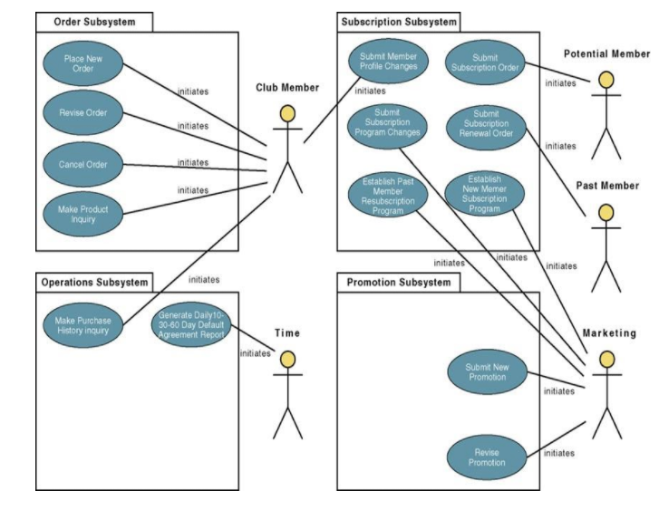
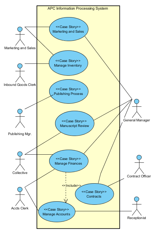
The use case diagram provides a richer scope representation than the context diagram because it provides a high-level look at the system’s capabilities, not just at its external interfaces. There is a practical limitation, though. Any sizable software system will have dozens of use cases, with many connections among them and between use cases and actors.
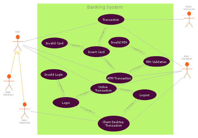
Use case context diagram
A UML use case diagram is the primary form of system/software requirements for a new software program underdeveloped. Use cases specify the expected behavior (what), and not the exact method of making it happen (how). Use cases once specified can be denoted both textual and visual representation (i.e. use case diagram). The context diagram of a vision document is a simple diagram that shows the source systems contributing data to a DW/BI system, as well as the major user constituents and downstream information systems that is supports. This simple diagram only takes a few minutes to draw once the project architect has completed all the research and the hard thinking that it represents. The Context Diagram: Getting Started with Use Cases. People new to use cases are often unsure of where to start gathering requirements. I suggest creating a context diagram. A context diagram is a high-level, informal view of three things: the system you're going to be gathering requirements for, the things that need to interact with the system ...
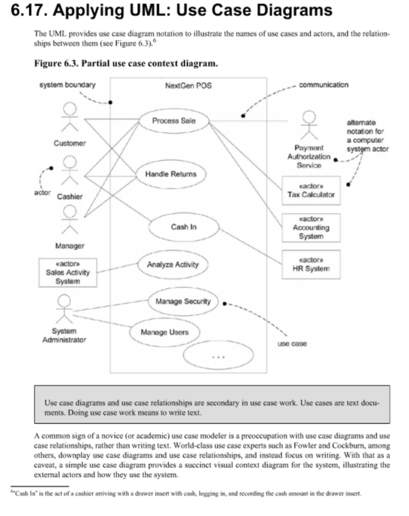
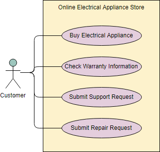
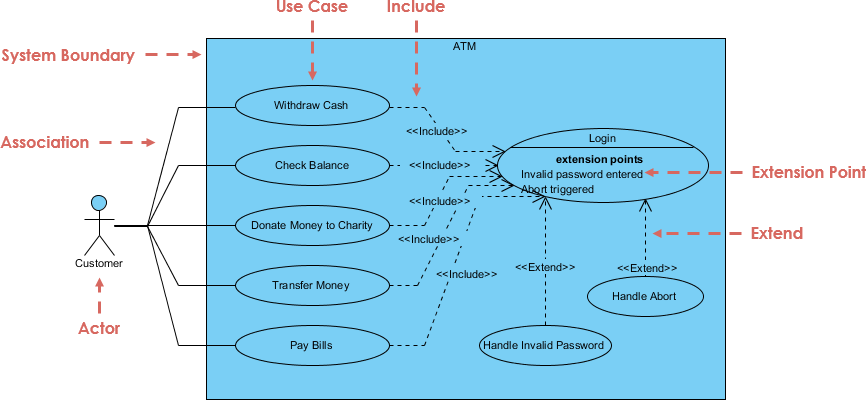
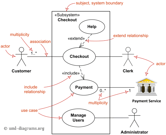
Use case context diagram. A use case diagram is an excellent picture of the system context; it makes a good context diagram, that is, showing the boundary of a system, what lies outside of it, and how it gets used. It serves as a communication tool that summarizes the behavior of a system and its actors. Use case diagrams are a way to capture the system's functionality and requirements in UML diagrams. It captures the dynamic behavior of a live system. A use case diagram consists of a use case and an actor. A use case represents a distinct functionality of a system, a component, a package, or a class. Given a system-any system-some things will live inside the system, some things will live outside it. For example, in a credit card validation system, you'll find such things as accounts, transactions, and fraud detection agents inside the system. Similarly, you'll find such things as credit ... A use case diagram is a dynamic or behavior diagram in UML. Use case diagrams model the functionality of a system using actors and use cases. Use cases are a set of actions, services, and functions that the system needs to perform. In this context, a "system" is something being developed or operated, such as a web site.
Use Case dapat mendeskripsikan tipe interaksi antara si pengguna sistem dengan sistemnya. Tentunya, use case diagram merupakan sesuatu yang mudah dipelajari. Langkah awal untuk melakukan pemodelan, tentu perlunya suatu diagram yang mampu menjabarkan aksi aktor dengan aksi sistem itu sendiri, seperti yang terdapat pada use case diagram. A possible context diagram for the Video-Rental LTD case study is shown below. Figure 6.8. A context diagram for Video-Rental LTD · The process of establishing the analysis framework by drawing and reviewing the context diagram inevitably involves some initial discussions with users regarding ... Context diagrams. A context diagram is a graphical representation of a system which must only use one process to represent the entire system and deliberately does not go into defining all the processes so as to prevent people getting bogged down in complex details at an early stage. Assignment help: Compare and contrast a context diagram (using data flow diagram (DFD) modeling) and a use case diagram (using unified modeling language (UML))? We ensure that all your instructions are followed to the letter. You are able to choose the level of interest; professional, college, or high school.
A UML Use Case Diagram showing Use Case Context Diagram. You can edit this UML Use Case Diagram using Creately diagramming tool and include in your report/presentation/website. The purpose of this brief article is to provide a simple example on how to link and verify four models: use case, data flow diagrams, entity relationship diagrams, and state diagrams. Note the word verify, not validate. Verify in this context means that the technique is consistent and complete, not that it reflects correct requirements. Problem Diagrams (Problem Frames): In addition to the kinds of things shown on a context diagram, a problem diagram shows requirements and requirements references. Use case diagram: One of the Unified Modeling Language diagrams. They also represent the scope of the project at a similar level ... Search Search in IBM Knowledge Center · IBM Knowledge Center uses JavaScript. Scripting appears to be disabled or not supported for your browser. Enable JavaScript use, and try again

Uml Use Case Diagram Banking System How To Create A Bank Atm Use Case Diagram Bank System Use Case For Bank System
A popular form of the use-case diagram may help summarize the interaction of actors with the system. This diagram is called a top-level use-case diagram, but as it’s very similar to a type of diagram that predates UML; often you’ll see it called by its traditional name: context diagram. This type of diagram, shown in Figure 8-7, displays ...
October 18, 2017 - Answer (1 of 6): 1. Data flow diagram talks about the flow of data, i.e. Input - a process that processes it - and output in a system or a portion of the system. There are various blocks explaining this in a typical DFD. DFDs generally related to the whole system or a major subsystem inside of a ...
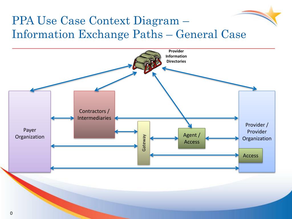
Ppt Ppa Use Case Context Diagram Information Exchange Paths General Case Powerpoint Presentation Id 2736295
A context diagram is a top-level data flow diagram. So why not create one by first creating lower level diagrams vs lower level use cases? There is a huge difference between use cases and data flow diagrams. With use cases, the analyst never knows if he/she is done with analysis. This a BIG problem in ultimately creating a context diagram.
Use case diagram (your example) support the context explicitly on the functional level. Use cases are elements of the system under development, while the actors are extern entities (systems or human users).
Use Case Diagram: Pengertian, Simbol, Komponen & Contohnya. Diagram use case merupakan suatu pemodelan yang bisa menggambarkan perilaku atau kebiasaan dari sistem yang ingin dibuat. Gambaran ini berupa interaksi dari satu actor atau lebih dengan berbagai sistem yang ingin dibuat ini. Dengan kata lain, use case diagram memiliki fungsi untuk ...
Introduction to System Context Diagram with Editable Examples. A context diagram is a visual representation of the relationship between data and business processes. This diagram has 3 main components which include external entities, system processes, and data flows. It provides the factors and events you need to consider when developing a system.
Use Case Diagram A Use Case Diagram is used to convey the use cases that a system performs and the actors that invoke and participate in those use ... of the system-under-design (SuD) within that context. It is not intended to be a precise specification of a behavior. Overview of SysML: A Sample Activity Diagram. Overview of SysML:
November 1, 2007 - It's tempting to consider use case diagrams as context diagrams because they do show context. But having one diagram for both will result in an unreadable cloud of bubbles, Kevlin Henney writes.
Use case diagram is a behavioral UML diagram type and frequently used to analyze various systems. They enable you to visualize the different types of roles in a system and how those roles interact with the system. This use case diagram tutorial will cover the following topics and help you create use cases better. Importance of use case diagrams.
Indeed, Use Case Diagram shows what we want the system to do rather than describe how it can be accomplished. One of the major benefits of this diagram is communication. Use Case Diagram Components. There are four major symbols in the Use Case Diagrams: Use cases, Actors, and Associations and System boundary. · Use Cases describe a sequence of ...
A use case diagram doesn't go into a lot of detail—for example, don't expect it to model the order in which steps are performed. Instead, a proper use case diagram depicts a high-level overview of the relationship between use cases, actors, and systems. ... Specifying the context and requirements of a system. Modeling the basic flow of events ...
1. Context Diagram 2. Use case descriptions and use case diagram 3. System sequence diagrams for each use case 4. User interface 5. Partition into major subsystems - show top-level decomposition and communication between these subsystems U Waterloo SE1 (Winter 2006) - p.34/38 SE 1 Process 1. For each subsystem, show in UML
• Context diagrams can capture interactions • Use cases can capture user and patient experience • Combining these with conventional requirements analyses yields a better product The following example describes a medical device, but the methodology applies more broadly to all healthcare processes .

Ppa Use Case Context Diagram Information Exchange Paths General Case 0 Payer Organization Payer Organization Provider Provider Organization Contractors Ppt Download
Use Case Descriptions • actors - something with a behavior or role, e.g., a person, another system, organization. • scenario - a specific sequence of actions and interactions between actors and the system, a.k.a. a use case instance • use case - a collection of related success and failure scenarios, describing actors using the system to

Figure 5 From An Extension Of The Use Case Diagram To Model Context Aware Applications Semantic Scholar
April 23, 2018 - A data flow diagram describes how information is shared (routed) through the various elements of your system. IT provides you with information as to the various types for objects these elements will…
Use Case Vs DFD, Difference in Use Case - DFD. Now a days almost all applications are based on OOP (object oriented programming); and use case diagrams depicts the functionality to be implemented in a system. On the other hand DFD (Data Flow Diagram) is the true depiction of OOP based programming.
The use case diagram provides a richer scope representation than the context diagram because it provides a high-level look at the system’s capabilities, not just at its external interfaces. There is a practical limitation, though.
Download scientific diagram | UML context diagram This sort of UML diagram can be created using the "use case" diagram editor of many mainstream UML modelling tools, but in fact doesn't share a lot of similarity with the standard use-case diagram. The key points about it are: • The system ...
December 17, 2014 - Requirements 12 Structured Analysis Method Structured system analysis and design (SSAD) – we will focus only on analysis Was used a lot when automating existing manual systems Main steps Draw a context diagram Draw DFD of the existing system Draw DFD of the proposed ...
The diagram is used to model the system/subsystem of an application. A single use case diagram captures a particular functionality of a system. Hence to model the entire system, a number of use case diagrams are used. Purpose of Use Case Diagrams. The purpose of use case diagram is to capture the dynamic aspect of a system.
A data flow diagram describes how information is shared (routed) through the various elements of your system. IT provides you with informat...
The Context Diagram: Getting Started with Use Cases. People new to use cases are often unsure of where to start gathering requirements. I suggest creating a context diagram. A context diagram is a high-level, informal view of three things: the system you're going to be gathering requirements for, the things that need to interact with the system ...
The context diagram of a vision document is a simple diagram that shows the source systems contributing data to a DW/BI system, as well as the major user constituents and downstream information systems that is supports. This simple diagram only takes a few minutes to draw once the project architect has completed all the research and the hard thinking that it represents.
A UML use case diagram is the primary form of system/software requirements for a new software program underdeveloped. Use cases specify the expected behavior (what), and not the exact method of making it happen (how). Use cases once specified can be denoted both textual and visual representation (i.e. use case diagram).

Verifying Use Cases Data Flow Diagrams Entity Relationship Diagrams And State Diagrams Via State Linkages


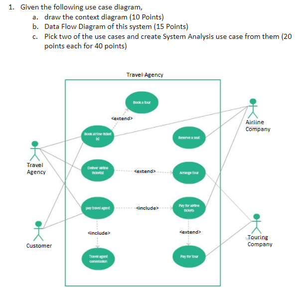











Comments
Post a Comment