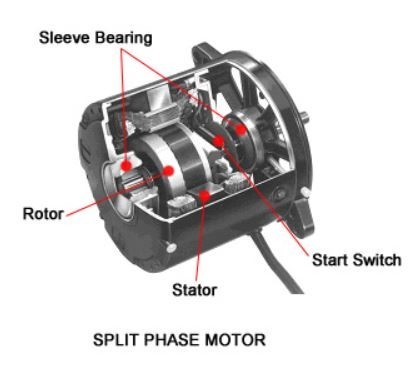
38 split phase motor diagram
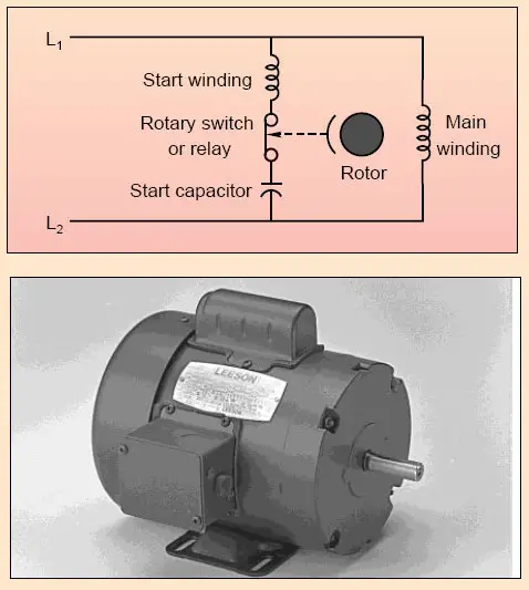
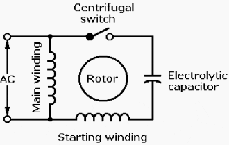
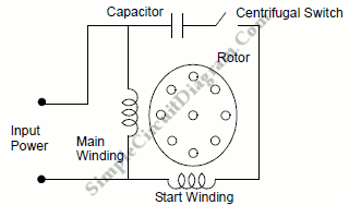
The Permanent Split Capacitor motor also has a cage rotor and the two The connection diagram of a Permanent Split Capacitor Motor is shown below. The permanent split capacitor motor is a simple, reliable design, because it has no starting switch nor a starting capacitor. A run type capacitor is connected in. The permanent split-capacitor (PSC ... The split-phase motor has the starting current about 7 to 8 times of the full load current. The starting torque of a split-phase induction motor is about 1.5 times of the full-load torque. The maximum or pull out torque is about 2.5 times of the full-load torque at about 75% of synchronous speed.
Single phase motors are not self-starting as the supply voltage is not producing a rotating magnetic field. Then how do the single-phase motors what we use everyday are self-starting? Read here to know about the split-phase motor wiring arrangement and starting method of a single-phase motor. Know the method used to reverse a single phase induction motor.
Split phase motor diagram
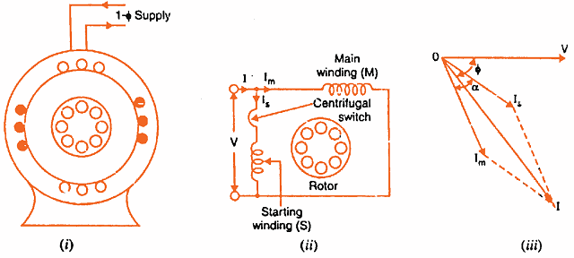
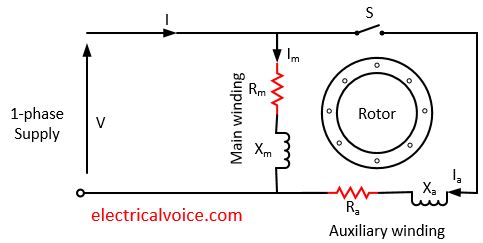
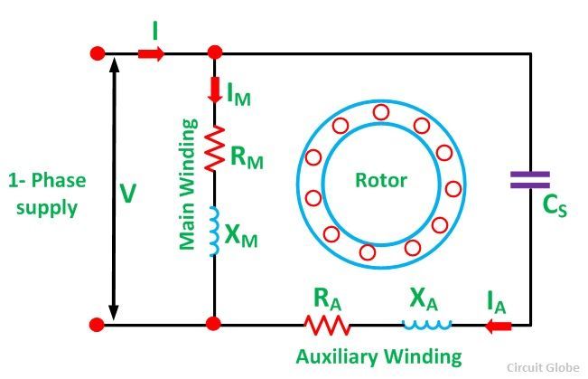
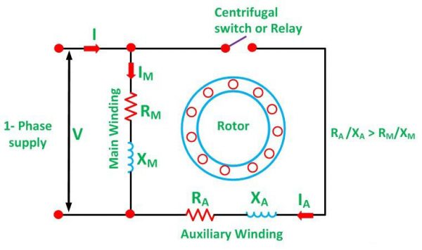
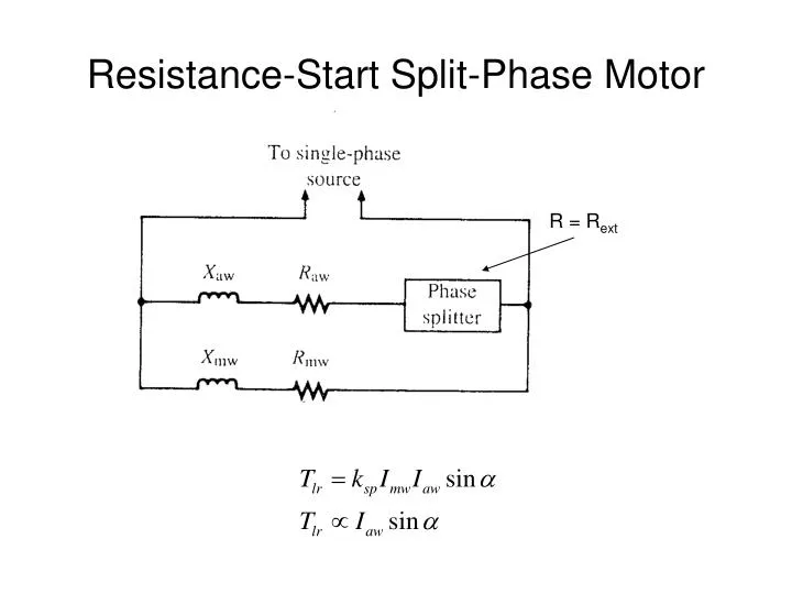
The circuit diagram of a permanent split-phase motor is shown in the figure below. The permanent split-phase induction motor consists of a squirrel cage rotor and the stator has two windings, viz. starting or auxiliary winding and main or running winding. The phasor diagram of the Split Phase Induction Motor is shown below: The current in the main winding (I M) lags behind the supply voltage V almost by the 90-degree angle. The current in the auxiliary winding I A is approximately in phase with the line voltage. Thus, there exists a time difference between the currents of the two windings. The split phase induction motor phasor diagram is shown below. The flow of current within the IM (main winding) can be lagged after the voltage supply ...
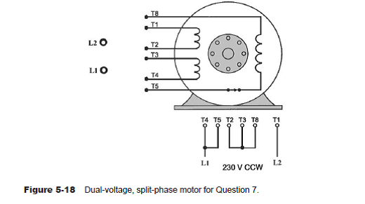
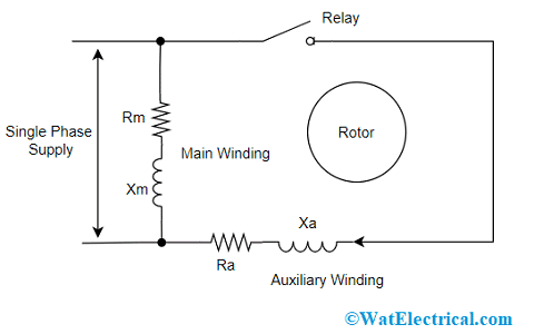
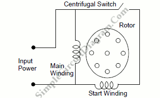
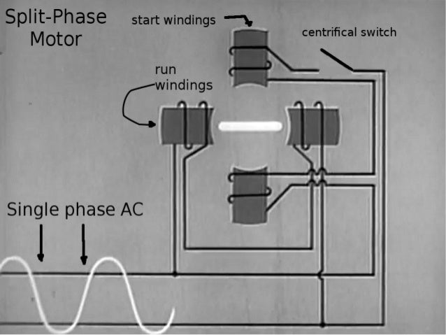
Split phase motor diagram. Diagram DD5 TWO-SPEED MOTORS For all other SINGLE-PHASE wiring diagrams refer to the manufacturers data on the motor. Diagram DD6 Diagram DD8 M 1~ LN E Diagram DD9 M 1~ LN E White Brown Blue L1 L2 N S/C Bridge L1 and L2 if speed controller (S/C) is not required Diagram DD7 LN E L1 L2 N S/C Z2 U2 Z1 U1 Cap. Thermal contacts (TB) white M 1~ Z2 ... The split-phase induction motor diagram is portrayed as below: Working of Split Phase Induction Motor Because of the non-uniform rotating field, the current across both the windings is not similar. So, starting torque is minimal which is almost 1.5 – 2 times more than initial running torque. Working of Split Phase Induction Motor In this topic, you study Split Phase Motor – Construction, Diagram, Working, Applications & Torque Speed Characteristic. These motors are commonly known as split phase induction motors or Resistance split phase Motors. The stator of this type of motor carries two windings, one called the main winding (M) and the Other known as auxiliary ... the 2 split phases L1 (Phase A, Red wire) and L2 (Phase B, Black wire) that are 180 degrees apart and which results in a lower current flow in the single common Neutral (this current will be = the difference in the currents in the two individual Split Phase Branch Circuits).
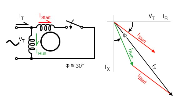
13 Apr 2021 — A split-phase motor has no capacitance in the auxiliary circuit. A phase shift to the main current is achieved by using narrow conductors to ... The Split Phase Motor is also known as a Resistance Start Motor. The stator of a split-phase induction motor is provided with a starting (or auxiliary) winding ... Split phase motor diagram is shown in the figure. I Run is the current in the main winding and I Start is the current in the starting winding. The angle between the two currents is φ as shown in the figure. Now the torque produced is such that it gives circular movement to the rotor. 5 Apr 2021 — In a split-phase induction motor, the starting and main current get split from each other by some angle, so this motor got its name as a ...
The split phase induction motor phasor diagram is shown below. The flow of current within the IM (main winding) can be lagged after the voltage supply ... The phasor diagram of the Split Phase Induction Motor is shown below: The current in the main winding (I M) lags behind the supply voltage V almost by the 90-degree angle. The current in the auxiliary winding I A is approximately in phase with the line voltage. Thus, there exists a time difference between the currents of the two windings. The circuit diagram of a permanent split-phase motor is shown in the figure below. The permanent split-phase induction motor consists of a squirrel cage rotor and the stator has two windings, viz. starting or auxiliary winding and main or running winding.







Comments
Post a Comment