39 water treatment process flow diagram
particles at higher water flow rates. The water must be pretreated - coagulated and flocculated - before passing through the filter bed. Such high rate direct filtration processes are widely applied to raw water with low levels of suspended matter. The diagram below shows the complete water treatment plant processes. Note: where coagulation, Take a look at the free customizable water treatment PID template provided for download and print. With it, you can create your own PID template quickly and easily. Basic electrical. 27230. 134. Electrical Wiring Diagram. 24870. 113. Producing PID.
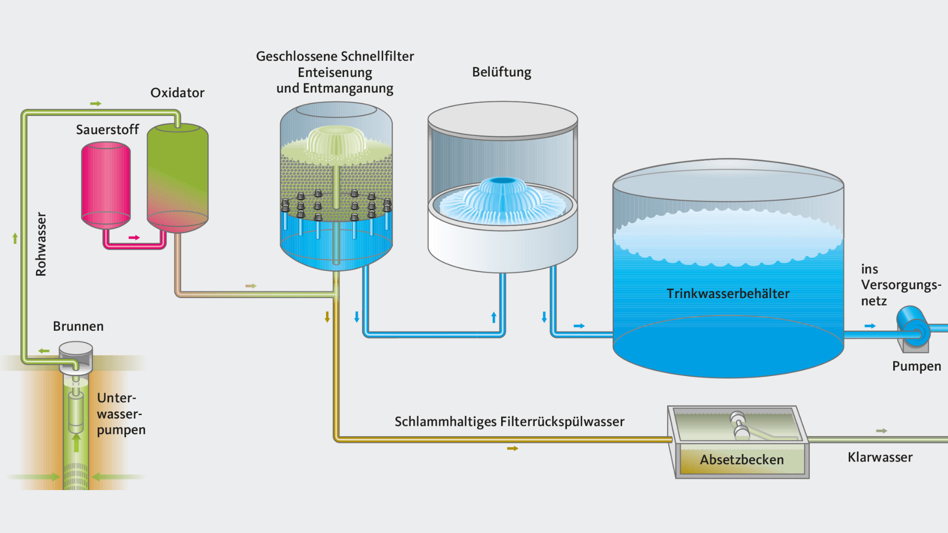
Figure 1: Flow diagram of pure water production (capacity max. 1200 m3/h pure water) At the Höchst Industrial Park, two pilot-scale plants are at present being operated to test river water treatment by ultrafiltration as an alternative to the multi-stage conventional process (see figure 2).

Water treatment process flow diagram
Download scientific diagram | Process flow diagram of the Mudor waste water treatment plant. from publication: Performance Assessment of the Rehabilitated ... Choice of Water Treatment Process Choice of treatment process depends on:Choice of treatment process depends on: Quality of raw water: Water sourceWater source Period of design year R i d lit f t t d t ( d )Required quality of treated water (end use) Economic resources available of O&M 5 Extracted from Prof C Visvanathan’s lecture notes Industrial Water Treatment Systems & Process Flow Diagram. These are existing Industrial Water Treatment Systems, they can be sized from 10 gpm to 250 gpm. With arsenic and uranium, contamination concentrations are important. At 25 ppb As I can run a system at 40 gpm, however at 120 ppb As I need to reduce it down to 10 gpm with the same system ...
Water treatment process flow diagram. Download scientific diagram | Flow diagram showing the process of wastewater treatment plant which consists of HF-UF filters (hollow fiber) and SW- UF (spiral wound), activated carbon and RO filters. The sampling locations in the plant are indicated by red printed Arabic numbers. from publication: ... Drinking-Water Treatment Plant (Process Animation): Animation of Process flow diagram of Drinking Water Treatment Plant is shown in this video. In Drinking w... Jun 06, 2018 · There is a growing concern about the occurance of pharmaceuticals in water bodies and in drinking water. Pharmaceuticals get into the water supply via human excretion and by drugs being flushed down the toilet. You might think wastewater treatment plants would take care of the situation, but pharmaceuticals pass through water treatment. Types of Membrane Housing in RO Skid: We can install Membrane housing in RO Skid with Vertical Feed Flow Horizontal Feed Flow Reverse Osmosis Plant Designing program. For Filmtec Membrane - ROSA (Reverse Osmosis System Analysis) design software For Hydronatics Membrane - IMSDesign Related Topics: Some Important guide to Design Reverse Osmosis plant In the […]
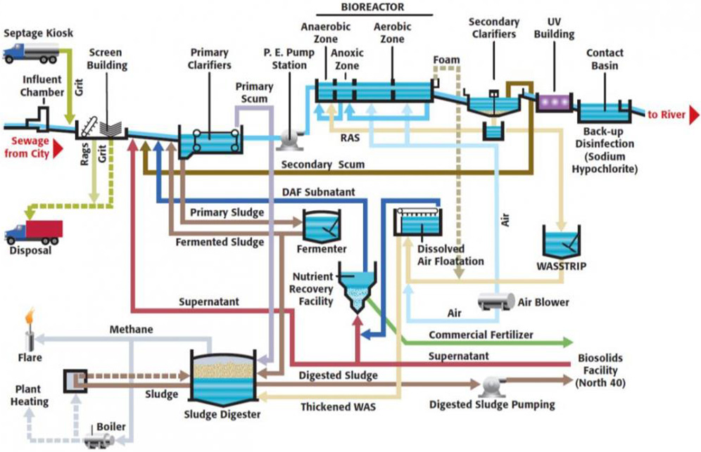
This page no longer exists or there is an error in the web address · Try checking the URL or search for the information using the search bar above The Singapore Stanford Partnership (SSP) educates Asia's best students in environmental engineering Wastewater Treatment PFD Template This PFD example is created using Edraw vector drawing software enhanced with PID solution. It shows the main process of waste water treatment visually. water to river • Sequence of unit processes: stabilization tank sedimentation biological process secondry settling nitrifier unit denitrifier unit disinfection discharge water suitable for river • Function of unit processes: making incoming flow rate uniform solid removal breakdown of organic compound settling of microbial biomass
Flow diagram showing the process of wastewater treatment plant which consists of HF-UF filters (hollow fiber) and SW-UF (spiral wound), activated carbon and RO ... October 31, 2020 - Download scientific diagram | Typical process flow diagram of a wastewater treatment plant (WWTP). from publication: Integration of Green Energy and Advanced Energy-Efficient Technologies for Municipal Wastewater Treatment Plants | Wastewater treatment can consume a large amount of energy to ... Oct 31, 2020 — PDF | This is my proposed process for treating oily wastewater. The initial Cod is 6000 mg/l and the oil and grease is : 2100 mg/L The ... Replacement Water Filters and Reverse Osmosis Membrane Drinking Water Systems and Parts. Low Prices and Same Day Shipping Since 1999. RO drinking water systems, faucets, tanks, valves, replacement water filter cartridges, water testing supplies, UV sterilizers, fridge filters and all service parts for your pure drinking water system.
Water Treatment Plant | Salmon Arm, BC - Official Website
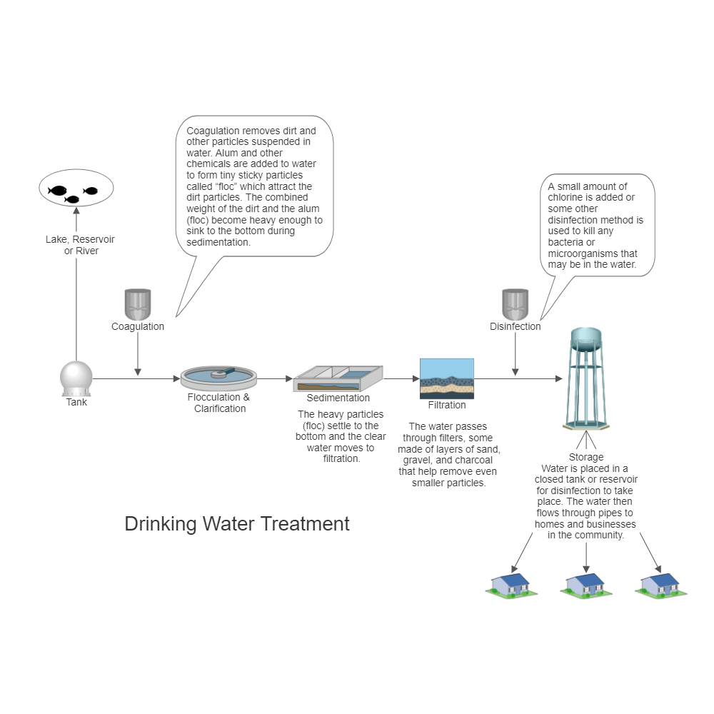
Text in this Example: Drinking Water Treatment Sedimentation The heavy particles (floc) settle to the bottom and the clear water moves to filtration. Storage Water is placed in a closed tank or reservoir for disinfection to take place. The water then flows through pipes to homes and businesses in the community. Flocculation & Clarification Tank Lake, Reservoir or River Coagulation Filtration ...

Sir Isaac Lowthian Bell Bt F.R.S. (1816-1904) by Henry Tanworth Wells - Town Hall, Middlesbrough
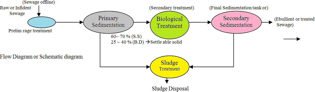
Sedimentation is a physical water treatment process using gravity to remove suspended solids from water. Solid particles entrained by the turbulence of moving water may be removed naturally by sedimentation in the still water of lakes and oceans. Settling basins are ponds constructed for the purpose of removing entrained solids by sedimentation.
Water | Free Full-Text | Design Aspects, Energy ...
Dec 20, 2018 · process flow diagram of effluent treatment plant (chart 3) Environment, Health & Safety committee made up to identify and resolve health and safety issues in the workplace. The Role of the committee in:

Pin by Rosemary Nmavulem Orlu, Ph.D. on desktop ...
Process flow diagrams PFDs are used in chemical and process engineering. The design process adopted here involves an evaluation of the expected wastewater flow site limitations and soil limitations to select size and position a waste treatment unit and land application system that will provide the best practical option.

journey of my engineering: Study of Waste-Water Treatment ...
In waste water purification microbial nitrogen rich carbon poor (or low C/N ratio) environments of denitrification process may serve as key to clean water. When C/N ratio is high causing short circuiting nitrogen cycle the objective of waste water treatment is defeated. 2. Treatment of waste and waste water from food industries:

Water treatment plant and sewage treatment and drinking ...
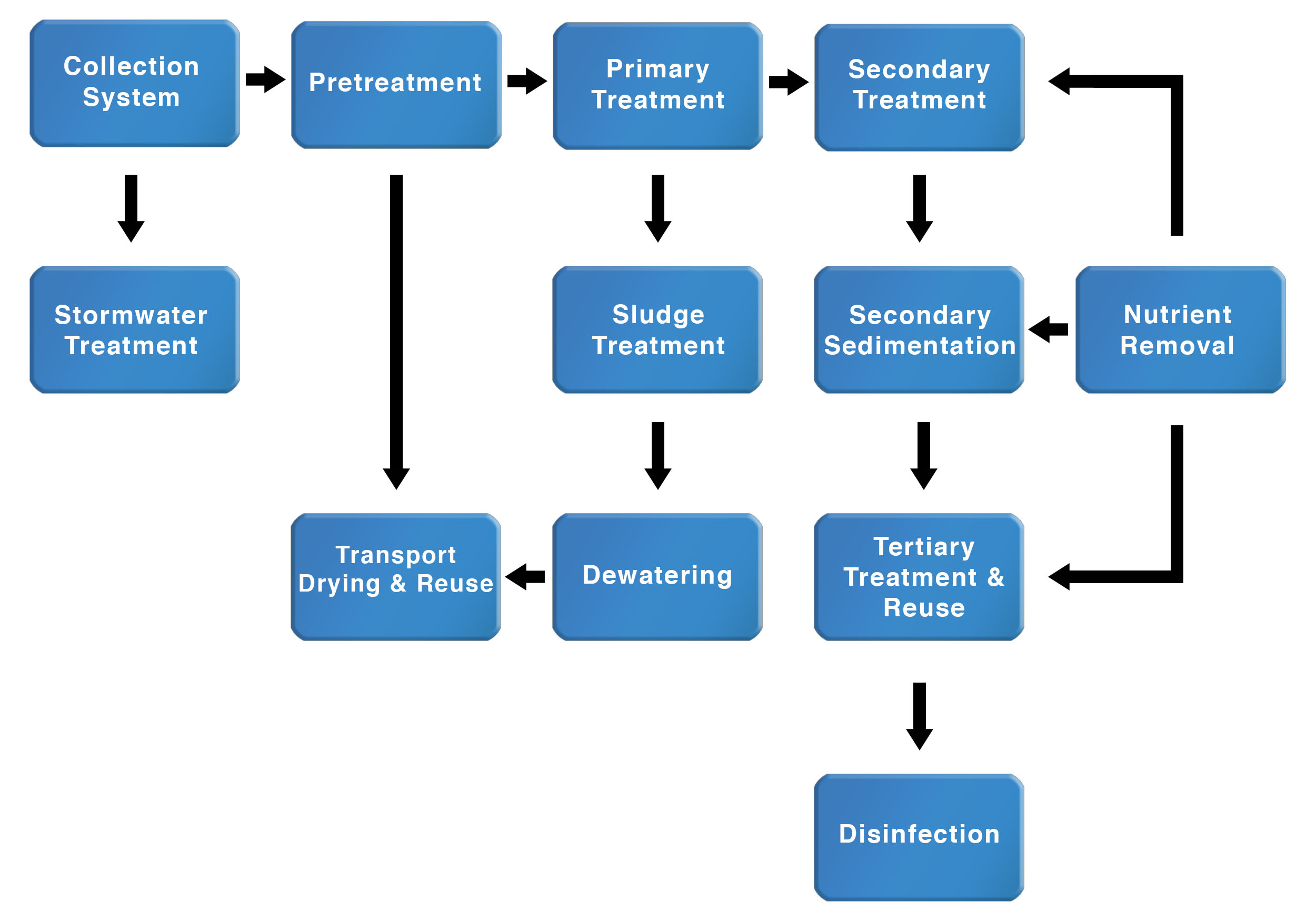
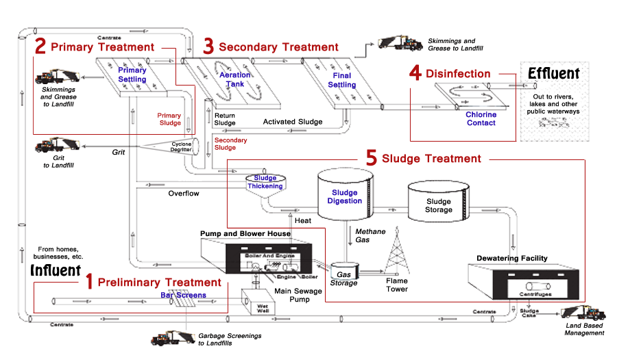
The secondary treatment (activated sludge process) is a biological phase. Air is introduced into the wastewater aeration tanks. The air flow stirs the wastewater and sludge, but it is the transfer of oxygen from its gaseous state to a liquid state that actually stimulates the growth of bacteria and other beneficial organisms that naturally ...

rebound
Download scientific diagram | Process flow diagram for water treatment process from publication: Treatment of water using watermelon (Citrullus lanatus) seeds as organic coagulant and microbial filter | This paper presents the treatment of municipality water using watermelon (Citrullus lanatus) ...

Belt Press Wastewater Treatment Plant Process Flow Diagram ...
A diagram of a caustic treatment unit is shown below. Figure 5. Caustic treating process xi Amine sweetening is a process whereby aqueous solutions of alkanolamines (such as ... A process flow diagram of an amine-sweetening unit is shown in Figure 6. ... the system then becomes unstable allowing the flow of water from the feed stream through ...

Make a splash.
the process of wastewater treatment and provides ... should flow into a storm water system and not into the sanitary sewer system. Unfortunately, this isn't always the case. ... Diagram of Wastewater Treatment Processes from "Clean Water For Today: What is Wastewater

Process flow diagram for full scale MBBR wastewater ...
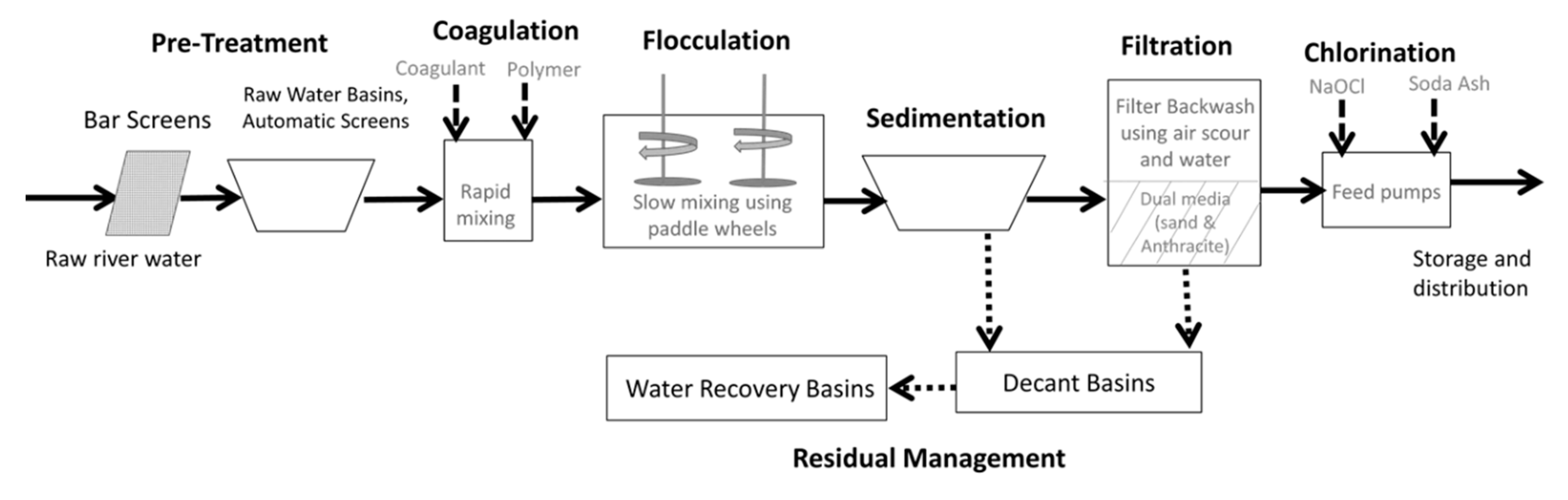
The water treatment process to deliver safe and wholesome water to customers includes many steps. Coagulation, flocculation, sedimentation, filtration, and disinfection are the water treatment processes that make up a conventional surface water treatment plant. These water treatment processes ensure that the water consumers receive is safe to drink and aesthetically pleasing.

Process Flow
the organic matter. The cleaner water trickles out through pipes for further treatment. From a trickling filter, the partially treated sewage flows to another sedimentation tank to remove excess bacteria. The trend today is towards the use of the activated sludge process instead of trickling filters. The activated sludge process speeds up the ...
Butterfly valves refurbished in Hamburg, Germany - AVK ...
4 process flow diagrams — desalination desalination — process flow diagrams basic swro process diagram intake screening facility pretreatment filters reverse osmosis drinking water supply tank outlet tunnel seawater concentrate outlet seawater intake intake tunnel seawater concentrate is safely returned to the ocean post-treatment to

Pharma Grade Salt - Edible Grade Salt, Mechanical Salt ...
diagram of a typical treatment plant is developed as an example, data input options are outlined, and a general description of how to use the program is provided. • Chapter 4 provides guidance for interpretation of the output from the WTP program.
Water Treatment Process Diagram - General Wiring Diagram
November 8, 2018 - Draw Layout of water treatment plant and explain functions of each unit. OR Draw a flow diagram showing components of water.

33 Water Treatment Process Diagram - Wiring Diagram Database
Learn about all that makes up the water treatment process including water sources, rapid mixing, flocculation, etc.
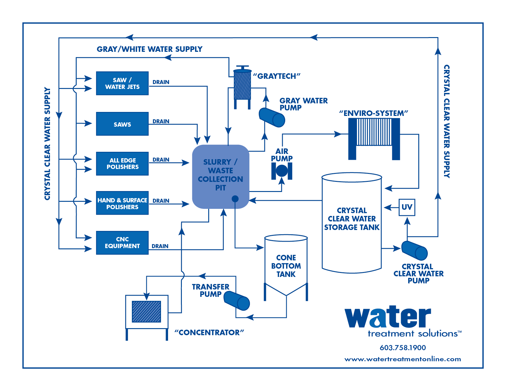
Flow Diagram - Water Treatment Solutions
Oil Sands Process Flow Diagram. Edit this example. Water Recycling Process Flow Diagram. Edit this example. Wind Energy Process Flow Diagram. Edit this example. Drinking Water Treatment Process Flow Diagram. Edit this example. Oil Refining - Hydrodesulphurization.
Drinking Water Treatment Process Flow Diagram
Download scientific diagram | Process flow diagram for Aspropyrgos Water Treatment Plant. from publication: Application of HACCP Principles in Drinking Water Treatment | One of the most important tasks at any water treatment plant is safeguarding the quality of drinking water.

2 Typical processes in water treatment plants | Download ...
The ORCA Sonar Bed Level System is one of our most popular products used throughout the water and wastewater industry. The ORCA Sonar Bed Level System will measure up to two density interfaces simultaneously. Typically these are bed levels / RAS blanket and floc / fluff layers. The sonar produces a high power concentrated beam, and provides ...

Underwater and lights
The Principle of Work : carbonic acidified water (through the dosing of CO 2) flows through a bed of crushed and sieved calcite, dissolving the carbonate minerals from the calcite packed bed.The carbonic acid is injected counter flow with the product water. This injection causes a vortex which ensures complete mixing of the carbonic acid with the process water.

I’m always mesmerized by the dance between light and water. I took this photo while waiting poolside for the models to set up during a styled shoot in Maui.
Helping you get safe and reliable energy · Helping you get local government services at a fair price
Basic Water Treatment - KNOXVILLE WATER TREAMENT | Water ...
Water Treatment Plant (WTP) process flow diagram. Modified from Cadmus (2003) and Brown and Caldwell (2011). TO. CONSTRUCTED. TREATMENT. WETLAND (CTW).
.png)
Decentralized Package Wastewater Treatment Plants
Objectives of the water treatment process. Some of the main objectives of the water treatment process are: 1. To reduce the impurities to a certain level that does not cause harm to human health. 2. To reduce the objectionable colour, odour, turbidity and hardness. 3. To make water safe for drinking. 4.

Water Treatment Process Flow Diagram - Ekerekizul
Jul 03, 2012 · This chapter covers different types of chemical process diagrams, how these diagrams represent different scales of process views, one consistent method for drawing process flow diagrams, the information to be included in a process flow diagram, and the purpose of operator training simulators and recent advances in 3-D representation of different chemical processes.

Surfing wave
The water treatment plant is a vital part of the dyeing section where the supply water of the dyeing floor is treated and cured for proper dyeing. The water available from different water sources cannot be used directly in boilers. The supply water contains various soluble effluents like dissolved solids, metal compounds, and other impurities ...

Process flow diagram of the water treatment pilot unit ...
Lake Nasworthy where it is transported down the Concho River to the water treatment plant. At the water plant, large pumps are used to transfer the water up to the treatment facility. Treatment facilities are often engineered to utilize gravity water flow as much as possible to reduce pumping costs.

Sunrise in Greece
sewage treatment wikipedia, process flow diagram for aspropyrgos water treatment plant, water treatment plant raw water treatment services, drinking water treatment plant process flow diagram, flow chart for effluent treatment plant etp auto garment
30 Water Treatment Plant Process Flow Diagram - Free ...
The wastewater treatment plant is designed to treat 250 gpm (56.8 m 3 h −1) of which 66% is recovered by the membrane processes and the rest through the brine evaporator/crystalliser unit (Fig. 5.6).The wastewater flow is generated by make-up RO reject (64%) (from make-up water plant), power block blowdown (22%) and mixed bed regenerate waste (14%).

Typical waste water treatment process. | Download ...
Jan 13, 2011 · Water Treatment Math Formulas Water Treatment Formulas 7 (3960) (Pump Eff., %, expressed as decimal) (Motor Eff., %,expressed as decimal) (Flow, gal/min) (Head, ft) Motor HP Pump Efficiency, %, expressed as a decimal (Water Horsepower) Brake HP Motor Efficiency, %, expressed as a decimal (Brake Horsepower) Motor HP X 100% Motor Horsepower

Ocean
4 Low Lift Pump Well These pumps lift the water to flow through the treatment processes by gravity. 5 Pre-oxidation & Primary Disinfection Disinfectants or other oxidants are added to disinfect or control tastes and odours. The specific processes used are determined by the chemical and biological raw water ...
Wastewater Treatment Process Diagram - Free Wiring Diagram
October 16, 2015 - Anaerobic filter consists of a column filled with solid media for the treatment of organic matter in sewage. In this process system, waste water (sewage) flows upwards through the column containing anaerobic bacteria. Due to the presence of solid media, the bacteria are retained in the column.

Process flow sheets: flowsheet of water treatment plant
Industrial Water Treatment Systems & Process Flow Diagram. These are existing Industrial Water Treatment Systems, they can be sized from 10 gpm to 250 gpm. With arsenic and uranium, contamination concentrations are important. At 25 ppb As I can run a system at 40 gpm, however at 120 ppb As I need to reduce it down to 10 gpm with the same system ...
Wastewater Treatment Plant | Saskatoon.ca
Choice of Water Treatment Process Choice of treatment process depends on:Choice of treatment process depends on: Quality of raw water: Water sourceWater source Period of design year R i d lit f t t d t ( d )Required quality of treated water (end use) Economic resources available of O&M 5 Extracted from Prof C Visvanathan’s lecture notes

Sir Isaac Lowthian Bell Bt F.R.S. (1816-1904) by Henry Tanworth Wells
Download scientific diagram | Process flow diagram of the Mudor waste water treatment plant. from publication: Performance Assessment of the Rehabilitated ...

Fuvahmulah maldives 🇲🇻

eYc FEM06 Electromagnetic Flowmeter industry application ...
Wastewater Treatment Process | Wastewater Treatment ...

Sewage treatment - New World Encyclopedia
Municipal Wastewater Treatment Plants - Treatment Process ...
Water Treatment Process | St. Cloud, MN - Official Website


Comments
Post a Comment