41 how to draw ts diagram
Aug 17, 2012 · To draw the head from any angle you must first understand its basic structure. Look past all the distracting details and visualize the underlying forms. This ability to simplify can be applied to the features of the face, but when starting the drawing you could look even further. For animal cell diagram (detailed) https://youtu.be/uySrC4RXgRwFor paramoecium diagram (detailed) https://youtu.be/-fKKgOVpjYFor detailed diagram of neuron ...
May 13, 2017 — And if you still don't understand, then just take a graph paper and draw the axes on it and label the X axis as V and Y axis as P. Now assume any value of ...3 answers · 6 votes: LETS TAKE AN EXAMPLE OF CARNOT ENGINE OR CARNOT CYCLE . The ideal gas relation PV=nRT. ...How can one take a P-V diagram and transform it into ...5 answersApr 11, 2016How do you draw isobaric lines in a T-S diagram ...2 answersMar 12, 2015How to understand T-S diagram of otto cycle - Quora2 answersMar 4, 2017If a TS diagram is circular, then what will be the shape ...1 answerAug 24, 2020More results from www.quora.com

How to draw ts diagram
An ideal gas is contained in a piston-and-cylinder device in which the system moves from state 1 to state 2.: a.) If T 2 is greater than T 1, show that the ΔS 12 is greater if the process is isobaric than if it is isochoric. Sketch the isobaric and isochoric process paths on PV and TS diagrams.: b.) Use your TS Diagram from part (a) to show that an isochoric path passing through a state has a ... Adiabatic: for which Q=0, so here the entropy would remain constant by definition (vertical line in T-S diagram). · Isothermal: for which T= constant, so we ...1 answer · Top answer: Elaborating on my comment: You're looking for the paths in the TS space for reversible isochoric and isobaric processes. It's important to specify ... The T-s diagram for a vapor-compression refrigeration cycle is shown below. Figure 1: Vapor-Compression Refrigeration Cycle T-s diagram Below is a possible CyclePad design of a refrigeration cycle. The layout shown below is a clickable image. To jump to the part of this page that details the assumptions of a particular device or statepoint ...
How to draw ts diagram. Draw Your Bridge to Scale. The next step is to draw your design out on paper. In a perfect world, you will make a full size drawing. This will make it much easier to build the bridge. But before you can draw your bridge, you must decide how big each piece (member) of your bridge will be. The diagram has an electronic pen that allows you to draw on it. This diagram will be used in Practice Quiz 3-4 and Quiz 3-4, so become familiar with it. The most recent Skew-T Log-P diagram created from the radiosonde launched from Pittsburgh, PA. The date can be seen in the bottom left, and the time is in UTC time. This tutorial explained how to plot T-s diagram in excel and using Aspen Plus to generate Thermodynamic Properties Draw the layout of the process on a paper scaling down to match the distance between each work point include all the equipment, walls, machinery, bins etc., ... Do’s and Don’ts of Spaghetti Diagram. Do’s. Follow the moment of each individual and keep the line flowing in a singular path;
The stress range diagram defined above is the Goodman diagram for fiberglass sucker rods and is used for the same purposes as the modified Goodman diagram for steel rods. Figure 3.72 gives this diagram for Fiberflex rods [84].These rods have a maximum allowable static load of 35,000. psi at a temperature of 160 F.. It can be observed that an increase in temperature or in … T-s diagram maker . Write state numbers. State change. Constant-pressure temperature change Isentropic temperature change (turbine/pump) Mixture change Isenthalpic Pressure change (valve) Export to image Stop drawing ... How to Draw a Sequence Diagram 97. long arrows, a natural aesthetic rule is to limit the maximal length of the ar-. rows, or at least to decrease the num ber of the longer arrows. The ... Drawing Anatomy for Beginners, Learning the Ins and Outs. When it comes to learning how to draw people successfully, knowing human anatomy is key. Jeff Mellem, artist and author of How to Draw People, shares the top dos and don'ts of drawing anatomy for beginner artists so you can start drawing more realistic figures in no time.
Q =⋅−TS S 0 21( ) (7-18) q = ⋅−Ts s 0 21( ) (7-19) 7-4 Isentropic process . ∆S = −= S S 0. 21 (7-13) (S const = during process) reversible adiabatic. Carnot Cycle . Q. Q net,in = W net,out. 3 . W net,out L = − QQ HL. Mollier diagram (Table A-10) h-s diagram is useful for analysis of steady-flow devices . 1. wh. S Area Q= S 1 S 2 1 ... Draw the pv and Ts diagram of four different thermodynamic processes keeping one constant at a time. Write the thermodynamic relations between these properties for each process. The slope and process path direction should be clear. Question: Draw the pv and Ts diagram of four different thermodynamic processes keeping one constant at a time ... Take R-22 Pressure-Enthalpy Diagram Figure 1-1, draw a condensing temperature line of 105ºF, an evaporative temperature line of -20ºF , constant throttling line from the 105ºF condensing liquid to -20ºF line to represent the expansion and draw the line of constant Electron orbital diagrams and written configurations tell you which orbitals are filled and which are partially filled for any atom. The number of valence electrons impacts on their chemical properties, and the specific ordering and properties of the orbitals are important in physics, so many students have to get to grips with the basics.

Thermodynamics eBook: Brayton Cycle
This is part of our collection of Short Problems. You may also be interested in our longer problems on Angles, Polygons and Geometrical Proof Age 11-14 and Age 14-16. Printable worksheets containing selections of these problems are available here:

Compare the Otto cycle and the Diesel cycle.*a) Draw the P-v ...
I would suggest commenting your TypeScript code using the JSDoc convention, compile your TS code without stripping off comments (removeComments to false in tsconfig.json), and use a documentation generator on the JS files. Based on that, you could maybe find a tool to generate UML diagram from JSDoc : JSDoc UML Diagram.

Brayton Cycle | Efficiency, P-V & T-S Diagrams | Heat & Work ...
Skew-T diagrams look pretty forbidding until they are explained to you, but, hopefully, I will provide enough guidance to enable you to take a quick look at them and draw conclusions about the kind of a soaring day is expected. Where to get the Sounding Data: One of the best Websites is Bill Moninger's FSL website
Heat Engines
A temperature-entropy diagram, or T-s diagram, is a thermodynamic diagram used in thermodynamics to visualize changes to temperature and specific entropy during a thermodynamic process or cycle as the graph of a curve.It is a useful and common tool, particularly because it helps to visualize the heat transfer during a process. For reversible (ideal) processes, the area under the T-s ...

Draw a device schematic and T-s diagram for a solar power ...
Draw a labelled diagram of the longitudinal section of a flower. - Get the answer to this question by visiting BYJU'S Q&A Forum.

Temperature–entropy diagram - Wikipedia
Rankine cycle - Ts diagram. The Rankine cycle is often plotted on a pressure-volume diagram (pV diagram) and a temperature-entropy diagram (Ts diagram).. When plotted on a pressure-volume diagram, the isobaric processes follow the isobaric lines for the gas (the horizontal lines), adiabatic processes move between these horizontal lines, and the area bounded by the complete cycle path ...
How to draw t-s diagram from p-v diagram? (with pictures ...
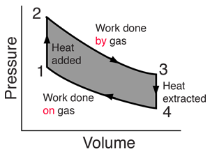
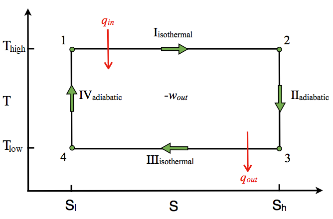
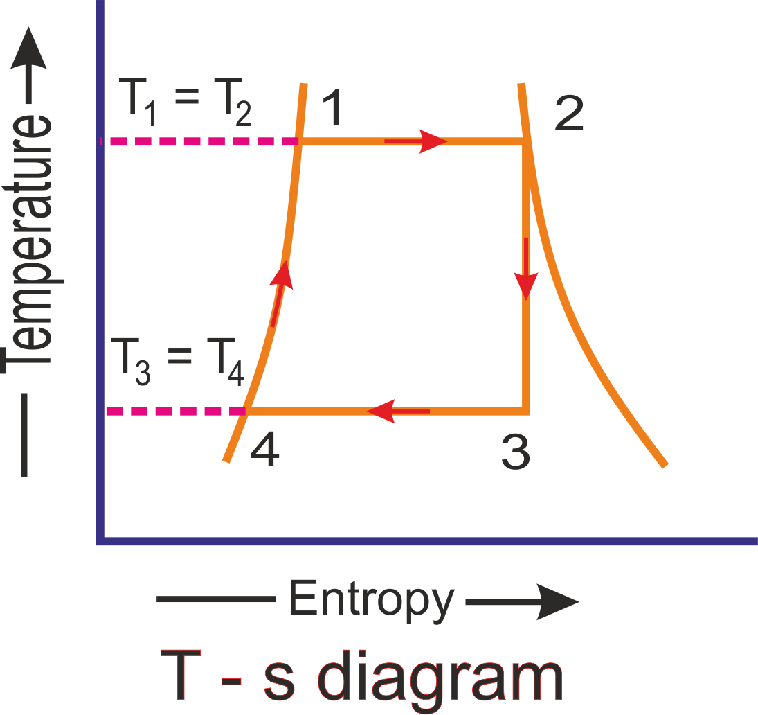
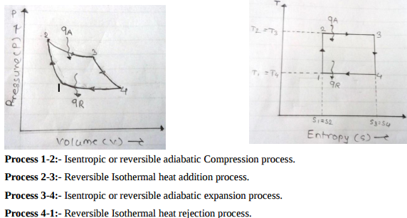
As we can see here from PV and TS diagram, there will be two reversible isothermal processes and two reversible constant volume processes. Process, 1-2: Isothermal expansion from state 1 to state 2. Heat energy will be added here from external source. Volume will be increased but pressure will be reduced during this process. ΔU = 0,
Carnot Cycle - Chemistry LibreTexts
A free-body diagram for this situation looks like this: 4. A skydiver is descending at a constant velocity. Considering the air resistance, the free body diagram for this situation would like the following: Free Body Diagram Solved Problem. Example: Draw a free body diagram of three blocks placed one over the other as shown in the figure. Solution:
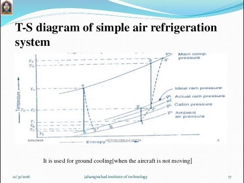
How to draw T-S diagram for simple air cooling cycle (HINDI)
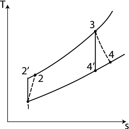
Answer (1 of 2): Here is a Ts diagram with all processes involving one constant state variable. Let's first remember that the definition for microscopic entropy states it is proportional to the amount of states (positions and velocities) the molecules can be in. * 1-2 is an isothermal heat add...
![Rankine Cycle - Processes, Efficiency [P-v and T-s Diagram]](https://www.theengineerspost.com/wp-content/uploads/2019/09/T-s-digram-of-Rankine-Cycle.jpg?ezimgfmt=rs:352x266/rscb19/ng:webp/ngcb19)
Rankine Cycle - Processes, Efficiency [P-v and T-s Diagram]
Draw P-H and T-S diagram when the vapours are superheated at the end of compression and with under cooling of liquid. written 4.9 years ago by shaikhrehan227 ♦ 230: modified 4.0 years ago by sanketshingote ♦ 740: Subject:-Refrigeration and Air Conditioning.
How to draw a PV diagram from a TS diagram - Quora
It was introduced by Helland-Hansen (1916). I am going to show you how to make the TS diagram in both python and R programming languages. In a T-S diagram, potential temperature (on the vertical axis) is plotted versus salinity (on the horizontal axis). I have a dataset containing surface temperature and surface salinity of 156 observations.
Solved How can I draw a p-v diagram of the real | Chegg.com
Answer (1 of 3): Hi Sucheta, If you are aware that, PV diagram are process specific, which means each process has it's own specific PV diagram. If you are aware of the kind of process, you will also be aware of how the properties like pressure,volume, temperature,entropy etc. change during the p...
How to draw isobaric lines in a T-S diagram - Quora
Show the cycle on a T-s diagram with respect to saturation lines, and determine i. The quality of the steam at the turbine exit ii. The thermal efficiency of the cycle iii.

COP Of Air Refrigerator Working On Reversed Carnot Cycle with ...
The temperature-entropy diagram (Ts diagram) in which a point specifies the thermodynamic state on a graph with specific entropy (s) as the horizontal axis and absolute temperature (T) as the vertical axis. Ts diagrams are a useful and common tool, particularly because it helps to visualize the heat transfer during a process.

p-v diagram for a pure substance | Download Scientific Diagram
May 13, 2021 · As described on the work slide, the area under a process curve on a p-V diagram is equal to the work performed by a gas during the process. On the right of the figure we have plotted the temperature versus the entropy of the gas. This plot is called a T-s diagram. Lines of constant pressure curve from the lower left to upper right on a T-s diagram.
Rankine Cycle - Ideal Rankine Cycle efficiency ...
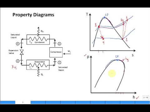
HVAC Drawing Templates SmartDraw Ts Diagram Of Vapour Compression Refrigeration Cycle. The T-s diagram for a vapor-compression refrigeration cycle is shown below. Figure 1: Vapor-Compression Refrigeration Cycle T-s diagram Below is a possible CyclePad design of a refrigeration cycle. The layout shown below is a clickable image.
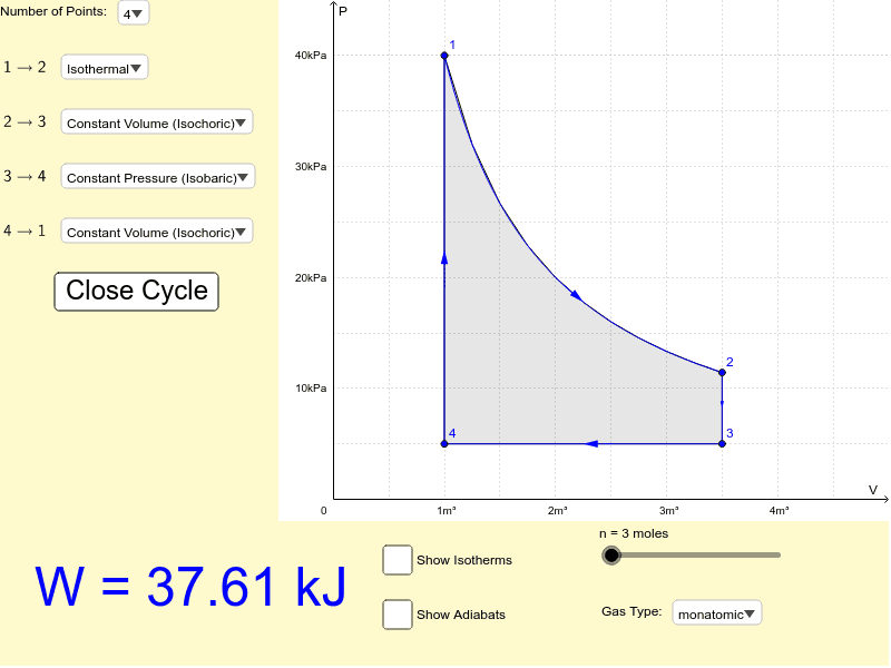
P-V Diagram and Work – GeoGebra
3. Thermodynamics Temperature-Entropy (T-s) DiagramA Ts diagram is the type of diagram most frequently used to analyze energy transfer system cycles. This is because the work done by or on the system and the heat added to or removed from the system can be visualized on the T-s diagram. By the definition of entropy, the heat transferred to or ...
Turbine Engine Thermodynamic Cycle - Brayton Cycle
The figure shows the corresponding P-V diagram. In this case, the work done by the gas on its surroundings, W = `∫_("v"_1)^("v"_2)"PdV"` ( = area under the curve) is negative. the volume of the gas has decreased from V 2 to V 1. Negative work with varying pressure. The figure shows the corresponding P-V diagram.
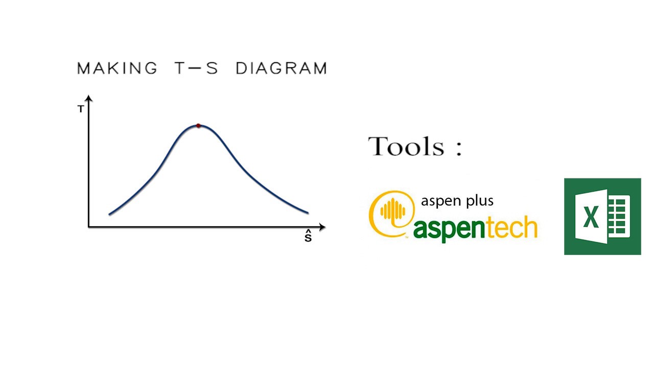
How to plot T-s Diagram (Using Excel And Aspen Plus)
Phase Diagram 1. Chapter-5 PHASE AND PHASE EQUILIBRIUM Prepared By: PALLAV RADIA Asst prof. AITS, RAJKOT. 2. Introduction: One of the most important objective of engineering metallurgy is to determine properties of material. The properties of material is a function of the microstructure which depend on the overall composition and variable such as pressure and …
The pressure-volume (pV) diagram and how work is produced in ...
Temperature Entropy (T-s) Diagram. A T-s diagram is the type of diagram most frequently used to analyze energy transfer system cycles. This is because the work done by or on the system and the heat added to or removed from the system can be visualized on the T-s diagram. By the definition of entropy, the heat transferred to or from a system equals the area under the T-s curve of the process.
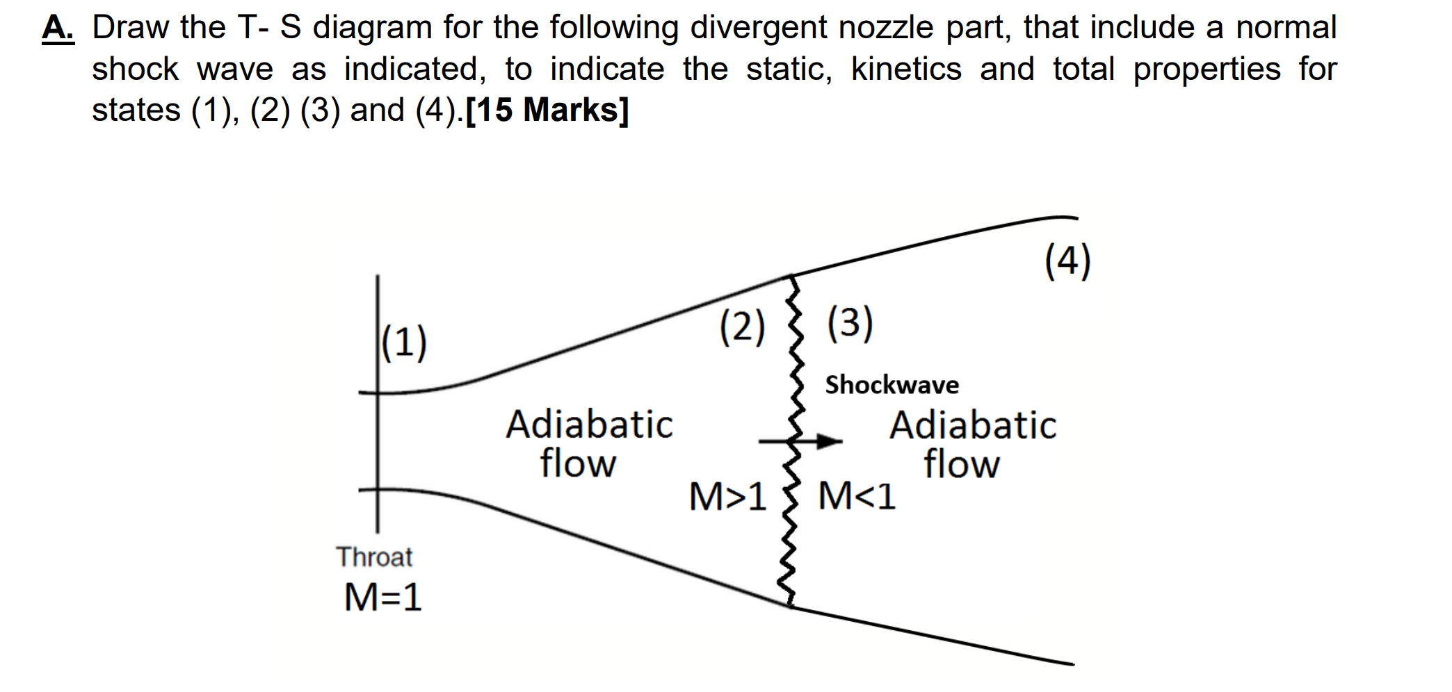
Solved A. Draw the T-S diagram for the following divergent ...
Popular Answers (1) It is very simple in EES. Edraw and similar software are used for drawing the cycle schematic diagram. While T-s and P-V diagrams can be drawn easily by EES using the cycle ...

The property diagrams of reversible Carnot cycle. (a) p-v ...
Brayton cycle actual diagrams equations Ts Pv formula The Brayton cycles are mainly used in jet planes, usefulness of this Cycle is tremendous due to the fact it is the backbone in driving even helicopters, and submarines.
![Rankine Cycle - Processes, Efficiency [P-v and T-s Diagram]](https://www.theengineerspost.com/wp-content/uploads/2019/09/p-v-diagram-of-rankine-cycle.png?ezimgfmt=rs:348x306/rscb19/ng:webp/ngcb19)
Rankine Cycle - Processes, Efficiency [P-v and T-s Diagram]
Rankine Cycle - Ts, Pv Diagrams, Reheat, Equations, Examples. Written by MechStudies. in Articles,Thermodynamics. Rankine cycle is explained along with T-s, P-v, diagrams, reheat, etc. All the formulas and examples are well captured to have a basic idea. Let's explore!

Brayton Cycle | Efficiency, P-V & T-S Diagrams | Heat & Work ...
The T-s diagram for a vapor-compression refrigeration cycle is shown below. Figure 1: Vapor-Compression Refrigeration Cycle T-s diagram Below is a possible CyclePad design of a refrigeration cycle. The layout shown below is a clickable image. To jump to the part of this page that details the assumptions of a particular device or statepoint ...

7: Rankine Cycle T-S Diagram with Irreversibilty Effect ...
Adiabatic: for which Q=0, so here the entropy would remain constant by definition (vertical line in T-S diagram). · Isothermal: for which T= constant, so we ...1 answer · Top answer: Elaborating on my comment: You're looking for the paths in the TS space for reversible isochoric and isobaric processes. It's important to specify ...
Turbine Engine Thermodynamic Cycle - Brayton Cycle
An ideal gas is contained in a piston-and-cylinder device in which the system moves from state 1 to state 2.: a.) If T 2 is greater than T 1, show that the ΔS 12 is greater if the process is isobaric than if it is isochoric. Sketch the isobaric and isochoric process paths on PV and TS diagrams.: b.) Use your TS Diagram from part (a) to show that an isochoric path passing through a state has a ...
Draw P-V and T-S diagram for carnot cycle. Name the processes ...
Cyclic processes and PV diagram for a cyclic process ...

Chapter 2a: Pure Substances: Phase Change, Properties ...

Shortcuts to convert P-v diagram into T-s diagram - EXERGIC

MOLLIER DIAGRAM
Draw the PV diagram for: (a) Isothermal process (b) Adiabatic ...

Chapter 2a: Pure Substances: Phase Change, Properties ...

HOW TO DRAW P-V AND T-S DIAGRAMS IN TELUGU

How to draw isobaric lines in a T-S diagram - Quora

Rankine Cycle - Ideal Rankine Cycle efficiency ...

What is Otto Cycle - P-V and T-S Diagram Easiest Explanation ...

T-s diagram of the vapour-compression refrigeration cycle ...

Stirling Cycle - Efficiency Explaination with P-v and T-s Diagram
How to draw a PV diagram from a TS diagram - Quora

How to draw a PV diagram from a TS diagram - Quora


Comments
Post a Comment