41 hydraulic motor diagram
I am not familiar with hydraulic systems. I have a question with regards to motor-hydraulic pump-hydraulic cylinder. For example, a hydraulic cylinder can lift a load at 10kg or 100kg at the same 0.1m/s. Regardless of the load, the volumetric flow rate stays the same because both cases they are moving at 0.1m/s. With the same flow rate in cylinder, the RPM in the hydraulic pump should be the same for both cases to output the same amount of flow. If the RPM of the pump is same for both cases, ... Hydraulic motor. The hydraulic motor symbol is similar to a pump symbol. The triangle inside the contour is rotated 180 degrees. Triangle shows the direction of supply of fluid to the hydraulic motor. In this case, the arrow indicates the direction of supply of fluid to the hydralic motor. If the symbol shows two triangles, it is a reversible ...
[https://www.ebay.com/itm/324864186925](https://www.ebay.com/itm/324864186925) $137.50 + Tax & eBay fees. Free shipping & shipped form TN, USA. Seller appears to have a few of them. Not to be confused with "MT5 eSTOP" which do not have the cutoff. MT5e's are usually out of stock and around $155. When it is in stock it's often overseas.
Hydraulic motor diagram
I've got a good set of hydraulic brakes, but i want the motor cutoff. I've come to find out that each manufacturer has their own proprietary way of connecting components and it's really frustrating. Anybody have a good solution? Any type of mechanical device that uses fluids to move or power something will contain hydraulic motors. They can be found in everything from a simple lifts system to heavy-duty equipment and wind turbines. Not only does this advancement make moving things easier, but the versatility of this system also makes it ideal for a large number of applications. [**Komatsu Final Drive Motors**](https://shophydraulicamerica.com/index.php/final-drives/komatsu.html) **What Are Hydraulics?** This system us... Hydraulic Motor A wide range of hydraulic motors Motorer.TIF Sauer-Danfoss is a world leader within production of low speed hydraulic motors with ... The fi nal motor size can be determined by using the function diagram for each motor size. • OMP and OMPW can be found on pages 18 - 23 • OMR and OMRW can be found on pages 45 - 49
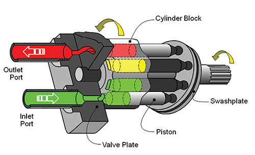
Hydraulic motor diagram. This drilling mud motor component consists of mud motor housing, mud motor steel stator, and mud motor elastomeric rotator. The positive displacement motor is a reverse application of the Moineau pump. Fluid is pumped into the motor progressive cavities. The force of the fluid movement causes the shaft to rotate within the stator as below figure. Engineering Essentials: Hydraulic Motor Circuits. Jan. 1, 2012. Driving a fixed-displacement fluid motor at constant pressure produces a constant torque drive, left. Used with a variable-volume pump to vary flow, the horsepower output of the motor varies with speed. If the load becomes excessive, pressure rises to actuate the pressure switch ... Electric, motor or a gas engine are used as the prime mover to rotate the shaft. The impeller blades are located on the shaft and the surrounding fluids will rotate with the movement of the shaft. ... A simple hydraulic pump diagram is shown in the figure below. Industrial Products Motors Issue 03/00 Size 50 to 11,600 cc/rev, up to 250 bar, 36,000Nm, 240kW Fixed Displacement Radial Piston Hydraulic Motor Staffa, Series B Data Sheet M-1001/03.00 GB Features Rugged, reliable, proven design. Unique Hydrostatic balancing provides minimum wear and extended life. High volumetric and mechanical efficiency.
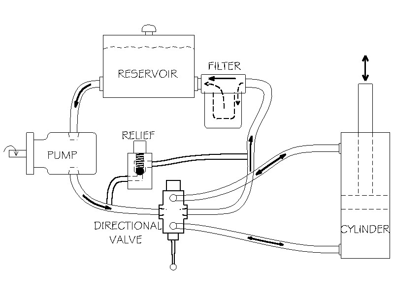
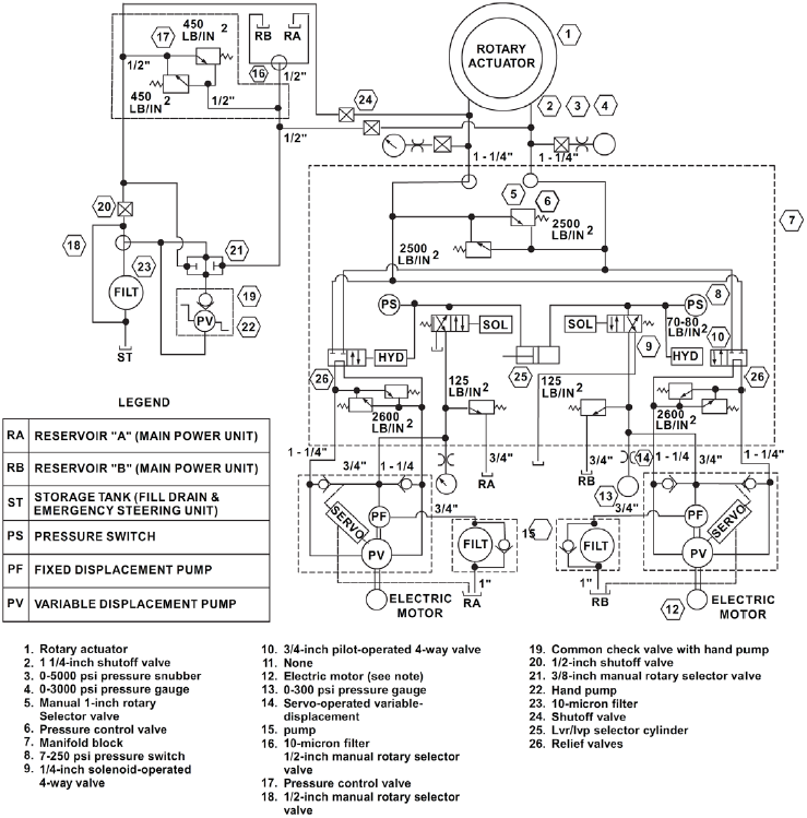
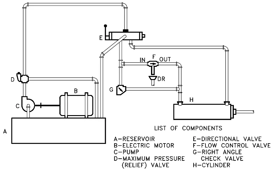
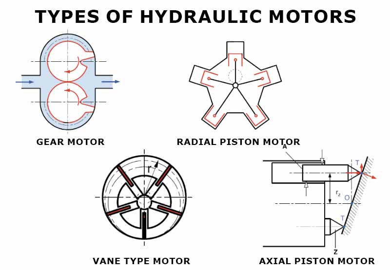
Hi Everyone, As the title suggests, I'm sort of theory crafting here and was looking for some opinions and resources for further research. Is it possible to install an electric motor on a drum containing a type of spooled pipe, so that these motors are essentially able to provide a 'back tension' whilst the pipe is either being spooled out of or onto the drum? So if the pipe is being spooled off of the drum, the motors are still able to provide back tension so that the pipe doesn't become loos... Figure 27 Simple Hydraulic Power System. Figure 28 Line Diagram of Simple Hydraulic Power System. With an understanding of the principles involved in reading fluid power diagram, any diagram can be interpreted. Figure 29 shows the kind of diagram that is likely to be encountered in the engineering field. Types Of Hydraulic Motors And Their Symbol Used in Hydraulic Circuit Diagram. 4. Hydraulic Cylinder. Hydraulic cylinder is a mechanical hydraulic actuator that converts hydraulic energy or hydraulic pressure into linear displacement. It consists of cylindrical barrel, piston and piston rod. Hydraulic Spool Valve Diagram Introduction: E -Type Features: In the neutral position , all oil ports closed, not flow . Functional characteristics: 1. The inlet and outlet ports of device are closed, hydraulic actuator can be fixed in any its' working mechanism position, and no movement or rotary further even if there is external force on it ...
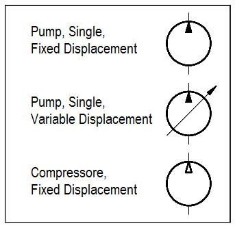
I was trying to understand the schematic of an hydraulic power unit operated by a bidirectional electric motor. Depending on the direction of rotation of the motor, fluid would flow out one port in the other but when the motor stopped no fluid would flow back into either port thereby holding the load. I am looking for suggestions for a electric motor that will be able to drive a 50 GPM hydraulic pump (I have been looking at this one: [https://www.ato.com/20-50-gpm](https://www.ato.com/20-50-gpm-hydraulic-gear-pump)). The optimal type of motor would be powered by DC. The end goal is to drive four 13 GPM hydraulic motors of this one pump. thank you! The most common units of motor displacement are in. 3 or cm 3 per revolution. Hydraulic motor displacement may be fixed or variable. A fixed-displacement motor provides constant torque. Controlling the amount of input flow into the motor varies the speed. A variable-displacement motor provides variable torque and variable speed. Hydraulic motors use pressurized hydraulic fluid to transfer power between pistons, turning the motor for more force and requiring less start up power. The pressurized fluid replaces gears and levers. This approach is known as mechanical replacement, and it helps to increase the start-up power of the motor.
A Quick and Easy Guide to Hydraulic Pump Technology and Selection
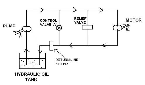
The diagram shows a winch powered by a hydraulic motor. The directional control valve with built-in relief features optional flow control to control the speed of the winch . The hydraulic pump and motor must be matched to the torque requirements of the winch.

Simplified hydraulic circuit schematic for the motor ...
Motors. Eaton's full line of hydraulic motors is backed by decades of proven reliability and performance under the toughest conditions and in the harshest environments. Get total confidence with the efficiency, durability, safety and speed of affordably priced Eaton Gerotor/Geroler®, gear, piston and vane motors to fit a wide variety of ...

Hydraulic Pump - an overview | ScienceDirect Topics
Hydraulic motors are powered by pressurized hydraulic fluid and transfer rotational kinetic energy to mechanical devices. D9 Series motors are the newest and largest members of the White Drive Products product family. The product is capable of producing torque values comparable to competitive motors, but with...

APU HYDRAULIC START MOTOR FLOW DIAGRAM
HYDRAULIC DIAGRAM 1 Motor 2 H.P. 8 Intake Check Valve Assem. 2 Pump 950101 3 Reservoir Assembly 705601 Ball Valve 586 4 Workhead 905051-S Valve Retainer 1953 5 Eductor Assembly 9 Check Valve Assem Nozzle 1287 Ball Valve 586 Eductor Body 2241 Spring 579 6 Release Valve Assem. Seat 1300

Simplified hydraulic circuit schematic for the motor ...
Products/Services for Hydraulic Motor Diagram. Hydraulic Motors - (362 companies) Hydraulic motors are powered by pressurized hydraulic fluid and transfer rotational kinetic energy to mechanical devices. Hydraulic motors, when powered by a mechanical source, can rotate in reverse direction and act as a pump.

How hydraulic starting systems work
Hydraulic Motor Function diagrams. 76 DKMH.PK.110.B4.02 520L0262 Explanation of function diagram use, basis and conditions can be found on page 7. • A: Continuous range • B: Intermittent range (max. 10% operation every minute) Max. permissible continuous/intermittent pressure drop for the actual shaft version can

Hydraulic symbology 206 – motors and actuators
FUNCTION DIAGRAMS 7 MOTORS MS MS 100 MS 80 M daNm GPMl/min GPM 0 0 300100 400 500200 p=275 bar 3990 PSI 140 bar 2030 PSI 105 bar 1520 PSI 70 bar 1020 PSI 30 bar 440 PSI n
Log Splitter Hydraulics and How It Works - Cylinder Services Inc
​ [T9 connects from SINPAC switch to ?](https://preview.redd.it/ftdgzxh6b4c81.jpg?width=1057&format=pjpg&auto=webp&s=5c10b64d8c1a0cab95ecdeb687d971c9cea07578)
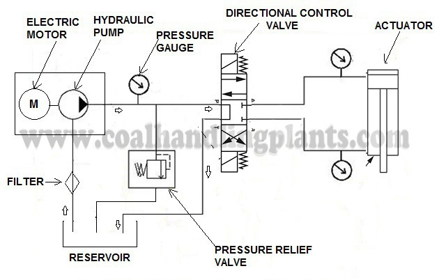
Basic Hydraulic System - Components / Parts,Design & Circuit ...
A hydraulic motor is a mechanical actuator that converts hydraulic pressure and flow into torque and angular displacement. The hydraulic motor is the rotary ...

Gerotor motors: 5 selection tips
Hydraulic Motors Hydraulic motors are rated in cubic inches per revolution. For example, a motor may have a displacement of 50 cubic inches. This means that 50 cubic inches of oil is required to rotate the motor shaft 1 revolution. The displacement affects the speedandtorqueamotorcandevelop. The larger the displacement, the more torque

What is hydraulic motor? - Quora
speed, high-torque hydraulic motors help you build a reputation for dependability. Our motors are designed and manufactured (speeds up to 2000 rpm and from 270-192,410 Nm [200-142,000 lb-in] of torque) to exceed the demanding requirements of the mobile and industrial industries.

Understanding and Troubleshooting Hydrostatic Systems
Block Diagram of Power to Hydraulic Pump. The Lippert Hydraulic Slideout and HLG System is an electric/hydraulic system. A . 12V DC electric motor drives a hydraulic pump that moves fluid through a.Ford Sport Trac with Multi Coil System , Spark Plug Wire Set by Beck Arnley®. Designed utilizing the latest technology, this product by Beck Arnley ...
Basic Diagrams and Systems | Engineering Library
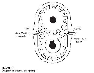
What is Gear Motor | Working , Diagram , Advantages ,Range. A gear motor develops torque due to hydraulic pressure acting against the area of one tooth. There are two teeth trying to move the rotor in the proper direction, while one net tooth at the center mesh tries to move it in the opposite direction. In the design of a gear motor, one of ...

hydraulic formulas & flow diagrams - ejuribe
the motor shown in the photo. Many hydraulic motors will have two larger hoses for the pressure and return lines and a small case drain hose. The smaller case drain hose carries fluid from internal motor leakage back to the reservoir. A small amount of internal leakage is designed in to these motors to lubricate and cool motor components.

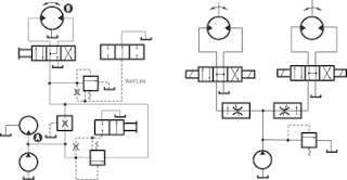
Operating Bi directional Motor using 4/3 DCV
Hydraulic connections -Applying the motor to the system 3 MOVING AND STORAGE Lifting - Shipping - Storage 2 GENERAL INFORMATION1. 0-2 RCOe2100/07.98 R C O ALZONI LEODINAMICA IVA. 0-3 R C O ALZONI LEODINAMICA IVA RCOe2100/07.98 Section 0 FOREWORD Contents 0.1 GENERAL SAFETY WARNINGS 0.2 DOCUMENTATION

Hydraulic Bent Axis Motors - Hydraulic Pump
"Hydraulics is a topic in applied science and engineering dealing with the mechanical properties of liquids. At a very basic level hydraulics is the liquid version of pneumatics. Fluid mechanics provides the theoretical foundation for hydraulics, which focuses on the engineering uses of fluid properties. In fluid power, hydraulics is used for the generation, control, and transmission of power ...
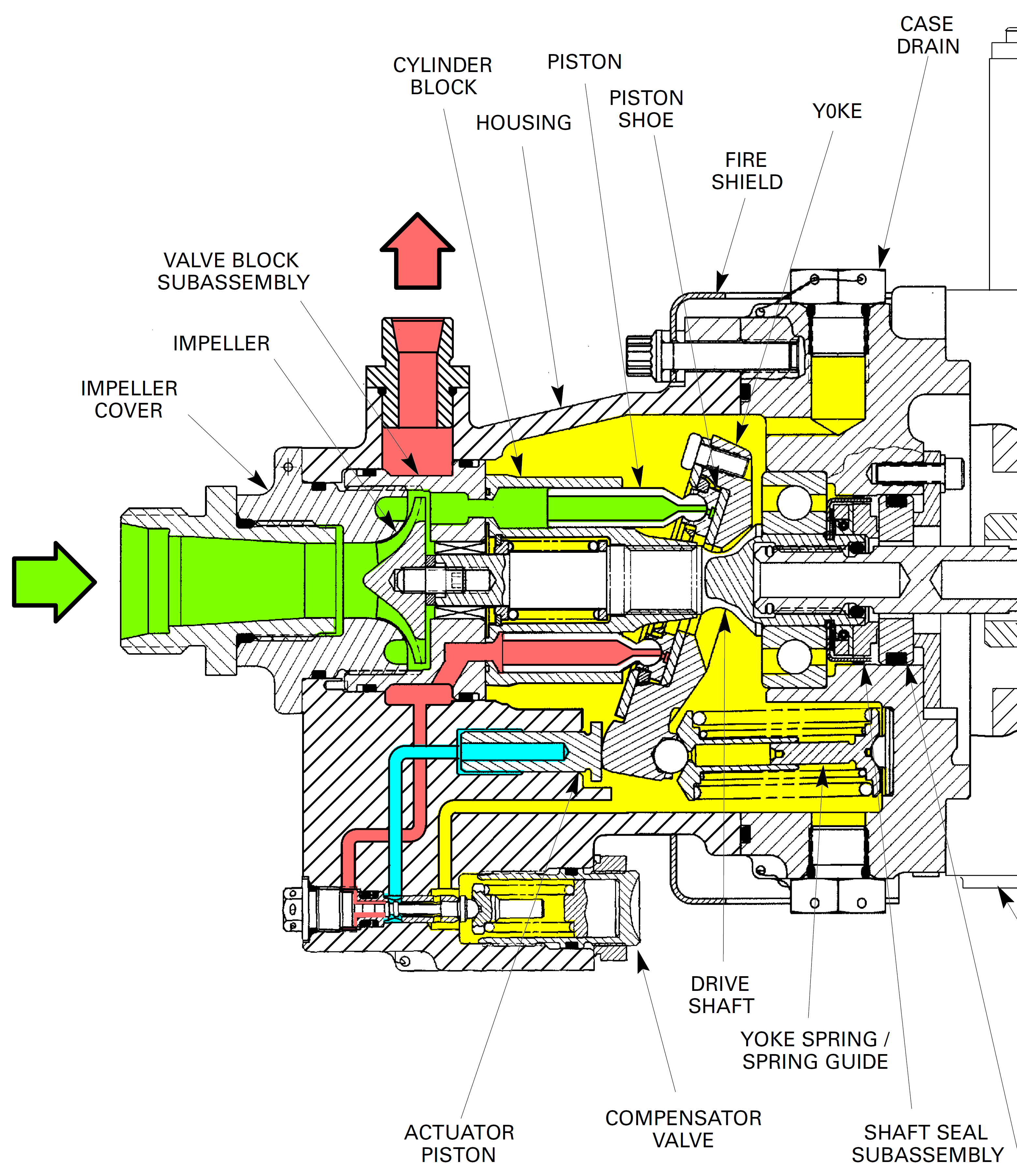
How does a pressure-compensated electric motor-driven axial ...
12 Volt Hydraulic Pump Wiring Diagram - 12 volt electric hydraulic pump wiring diagram, 12 volt hydraulic pump wiring diagram, Every electric structure is made up of various distinct parts. Each component ought to be placed and connected with different parts in particular manner. Otherwise, the arrangement won't work as it ought to be.

Machine Drawing: Hydraulic motor
Piston Motor | Types , Diagram , Working , Advantages Introduction to Piston Motor : Piston motors are positive displacement motors which can develop an output torque at the shaft by allowing pressurised fluid to act on the pistons. The piston motors can be either fixed or variable-displacement devices.
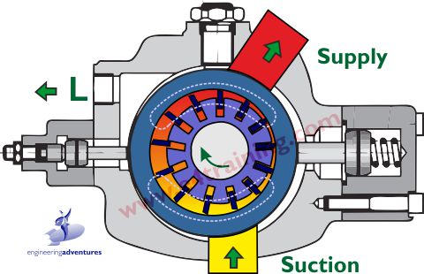
Hydraulic Vane Pumps and Motors
I am not familiar with hydraulic systems. I have a question with regards to motor-hydraulic pump-hydraulic cylinder. For example, a hydraulic cylinder can lift a load at 10kg or 100kg at the same 0.1m/s. Regardless of the load, the volumetric flow rate stays the same because both cases they are moving at 0.1m/s. With the same flow rate in cylinder, the RPM in the hydraulic pump should be the same for both cases to output the same amount of flow. If the RPM of the pump is same for both cases, ...

Hydraulic Motor Circuit | ManufacturingET.org
Hydraulic Motor A wide range of hydraulic motors Motorer.TIF Sauer-Danfoss is a world leader within production of low speed hydraulic motors with ... The fi nal motor size can be determined by using the function diagram for each motor size. • OMP and OMPW can be found on pages 18 - 23 • OMR and OMRW can be found on pages 45 - 49

Fundamentals of Hydraulic Motors | Power & Motion
Any type of mechanical device that uses fluids to move or power something will contain hydraulic motors. They can be found in everything from a simple lifts system to heavy-duty equipment and wind turbines. Not only does this advancement make moving things easier, but the versatility of this system also makes it ideal for a large number of applications. [**Komatsu Final Drive Motors**](https://shophydraulicamerica.com/index.php/final-drives/komatsu.html) **What Are Hydraulics?** This system us...
Hydraulic Motor - Open Source Ecology
I've got a good set of hydraulic brakes, but i want the motor cutoff. I've come to find out that each manufacturer has their own proprietary way of connecting components and it's really frustrating. Anybody have a good solution?

Hydraulic Motor - an overview | ScienceDirect Topics

Hydraulic Motor Types and how are they work? hydraulic motors and pumps

Hydraulic motor - Wikipedia
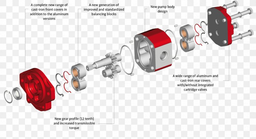
Gear Pump Hydraulic Pump Hydraulics Hydraulic Drive System ...
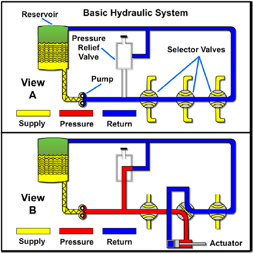
Basic Diagrams and Systems | Engineering Library
Hydraulic and Pneumatic P&ID Diagrams and Schematics - Inst Tools
Hydraulic and Pneumatic P&ID Diagrams and Schematics - Inst Tools

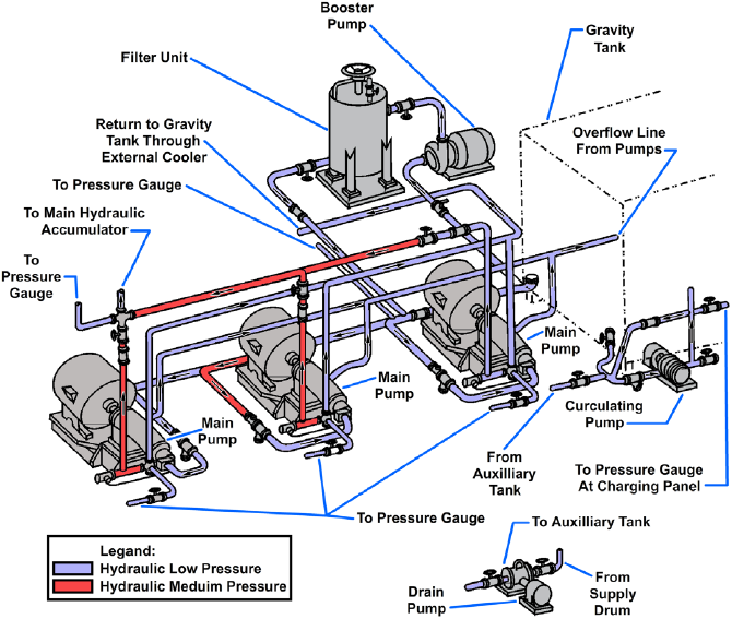
Aircraft Hydraulic System Pumps

What is a Hydraulic System | How does a Hydraulic Pump Work?
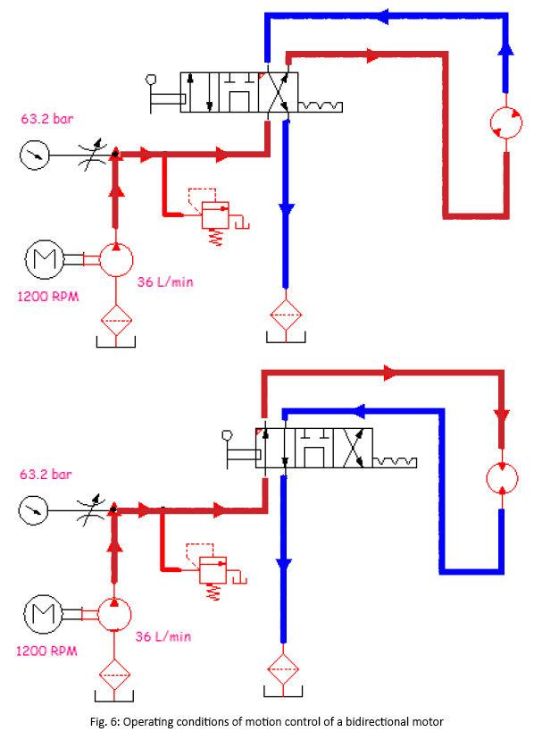
Motion Control of a Unidirectional and Bidirectional Motor ...
basic hydraulic circuit Archives - Marine Engineering Study ...
Basic Diagrams and Systems | Engineering Library
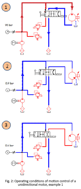
Motion Control of a Unidirectional and Bidirectional Motor ...

Basic Hydraulic System - Components / Parts,Design & Circuit ...

Difference Between Hydraulic motor and Hydraulic Pump

What are hydraulic motors?
Engineering Essentials: Hydraulic Motor Circuits | Power & Motion

How Hydraulic Pumps Work
Hydraulic Motor Types - A Detailed Guide - Workshop Insider


Comments
Post a Comment