43 electronic rat trap circuit diagram
Low Voltage Vs High Voltage Motor Wiring - Wiring Diagram Wiring Diagram For Low Voltage Motor Basic Electronics Wiring Diagram. Where Can I Find Circuit For Electronic Rat Trap Page 1. Motor Wiring Installation Tips Electrical Construction. Electricalsupplies Com. Wiring Motors High Or Low Voltage Electrician Talk. How to make electronic rat traps | eHow UK Use a cloth strip stapled to the trap floor to secure the capacitor in place. Repeat the process on the other side of the board by securing the (4) D Cell Batteries in the same manner. Keep all "+" and "-" ends together, which helps in the wiring of the electronic rat trap.
Squirrel Zapper Circuit Diagram - schematron.org Ovinm Electronic Rat Trap Powerful High Voltage Automatic Rat Zapper, Animal Trap to Get Rid of Rats and Mice, Squirrels and Rodents,Indoor/Outdoor Rat Catcher, Efficient, Safe and Clean. In the Republic of Ireland, the native red squirrel is protected, and since it feeds on nuts and seeds, it is not much of a nuisance.
Electronic rat trap circuit diagram
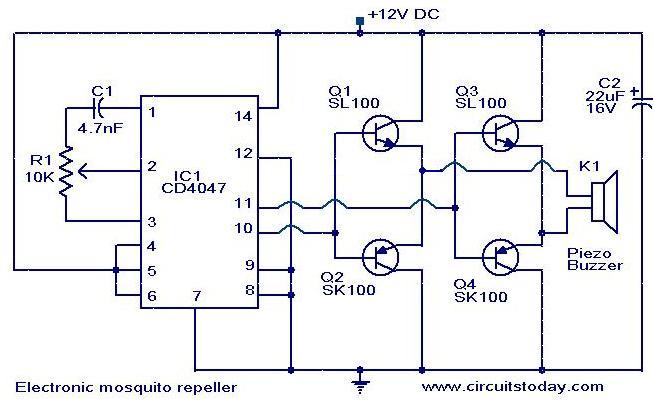
Mouse and Rat repellent circuit using astable multivibrator As Figure 1 in this circuit will have two monostable multivibrators. In frist set will consists of TR1 and TR2 are used to generate a low frequency by have C2, C3, R1-R4, LED and VR- 100K, which it is the frequencies generators to Collector of TR2. LED will is used for power on display of this project. And VR-100K will be adjustable of timing range. The low frequency will be sent to control the high frequency generator. Which consist of TR3 and TR4 and R5-R8, C5, C6 will be combine to increasing frequency rises up. Before send to piezo speaker next. In this the frequency generator will work according to the rhythm, The performance of low-frequency generator. We heard a sound out of the speakers at intervals. Simple Rat Repellent Circuit - Making Easy Circuits Nov 04, 2020 · This electronic rat repellent circuit really is easy as it simply works with a several unique variations of components. Therefore to suit your needs who may be presently studying, researching electronics, may make an effort to practice causes this circuit as it is regarded as less difficult for newbies. High Voltage Pulse Capacitor Rat Trap - Blogger Victor Electronic Mouse Trap In Action With Motion Cameras Full Review Mouse Trap Mondays. Greensource. ... Electronic Pests Killing Lamp Circuit Diagram 6. Synchronized Stimulation And Continuous Insulin Sensing In A. Best Mouse Zapper Near Me And Get Free Shipping A229.
Electronic rat trap circuit diagram. DC circuit for rat killer | Page 2 | Electronics Forum ... I searched and search, never found a homemade electric rat trap, other than wiring them up to the mains. I remember seeing somthing simalar to your bucket trap in a farming magazine years ago. I don't remember the specifics, but it used an electric fence charger to cause the rat or mouse to... RID-O-RAT Homemade Electronic Pest Control Device This is my homemade rat zapper that I was forced to make a while back because I had a problem with 2 rats that found their way into our home, chewed up expen... how to make electric mouse rat trap / high voltage | Simple ... Hello guys in today i will show you how to make Rat Trap with Electric Battery 3.7volt to 400000 volts This Amazing Invention You Can Make At Home its ver... ️ How to Make Best Homemade Rat Trap to Get Rid of Nasty ... 1. Make a bucket & spoon rodent trap. This is a domestic rat trap made from a ladle and a spoon. It is known as one of the best homemade traps. For a good result, you only require a huge bucket, a spoon and some bait such as peanut butter. By the way, you can make a peanut butter for rat bait yourself in less than 15 minutes.
Electronic Mouse Trap - Zen Internet An added feature is that multiple mouse traps can be monitored. Simply build more identical circuits and tune them to the same transmitting (RF) frequency. R2 must be set different in each case so that a different note is heard for each mouse trap. If two traps activate simultaneously then a "beat" note will be heard which will be the sum of ... How to make a mouse electric shock Trap & Circuit Diagram ... Hello! now i just want to make Diagram that show the guide about How to make a mouse electric shock Trap,An Animal electric shock trap , Diagram For How to Make A high Voltage Mouse Trap . via this images and video , i hope it can help you know clear the way and componnents […] DC circuit for rat killer | Electronics Forum (Circuits ... Jul 09, 2008 · Anyway, the electronic rat traps work, and the rat doesn't get a chance to snack on the bait. I've been using pepperoni dog treats, only had to replace twice. The first one I bought was under $30 at Home Depot. Went back a month later, $39.95. The second one hasn't kill a rat, but the bait remains. Rat zapper - All About Circuits Sep 28, 2013. #4. THE_RB said: Possibly the best way to get rid of mice and rats is to remove their food source, they eat a lot of calories so they only breed and thrive when there is a food source. Things like open bags of chook food, dry dog food, grains, open trash containers are what attracts the rats and allows them to breed up.
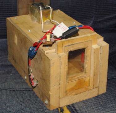
Electronic Pest Repellent Circuit - ElectroSchematics.com This pest repellent circuit has not been tested! Caution! This is a powerful ultrasonic pest repellent circuit so use it only in outdoor places. Do not use this ultrasonic pest repeller near babies or animal pets. Electronic Pest Repellent Circuit Diagram 1st Rat Trap - Nghia Ho I wanted a trap that did not require the mouse to exert any force. Using a laser tripwire was an obvious solution. A laser is projected onto a light sensor. When the mouse crosses the laser and breaks the beam, the circuit will activate an actuator and trap the mouse. The trap was built from MDF wood and electronic parts bought from Jaycar. Building your Own Zapper - Ryan McGinty did not want to copy his design. The circuit itself is a well-known electronic circuit freely available. Q: Will the circuit be damaged if I short-circuit the coins or Sp output? A: No, the output is protected by resistors to limit the current drain. Q: Will the NE555 component be damaged if I power it the first time with a faulty wiring? DIY Electric Shocking Mouse/Rat Trap - Electronics Forums Mar 5, 2018. So we live on a farm and have a problem with rats and mice in our barn. they need to go. we have tried several trap and no luck. I stumbled across some designs for electric shocking mouse traps. they look very simple. They used a pack to hold 4 "AA" batteries and a Voltage generator. I have attached a picture of the mouse trap I made.
DC circuit for rat killer | Electronics Forum (Circuits ...
How Do Electronic Mouse Traps Work? - Expert Advice The electronic mouse trap I bought had no info about bait, and I never would have seen the teeny space for bait without reading your article.I Thanks again and have a great day ! Steven_Smith. April 4, 2019 at 9:25 pm Hello Debbie, I am happy that it helped you in some way. Please let us know, what you do you want to know more about the traps ...
![Smart Rat Trap - Make: Volume 43 [Book]](https://www.oreilly.com/library/view/make-volume-43/9781457193934/graphics/f0072-01.jpg)
Smart Rat Trap - Make: Volume 43 [Book]
Circuit Diagram (wired operation) at a site with better cell reception or at a site central to several traps. One X'mtr and four R'cvr's could potentially activate 4 different trap gates or other devices on one trap. 12 gauge stranded wire Page - 2 Receiver has to be put in "learning" mode to select which channel of 10 thru 13, to use. (other channel) 433Mhz 433Mhz "B2" 24 ...

Victor Rat Zapper Ultra-Rodent Trap, RZU001-4
Owltra Mouse Trap - Electric Rat Zapper Quickly eliminate rodents in seconds. The Quick-Zap system generates up to 9,000 volts for a 100% extermination rate. NO TOUCH. NO MESS. Pull and remove the top for no-touch, no-see, no-mess disposal. With built-in safety sensors, you can easily access and clean the chamber in between uses.
Todays Circuits ~ Engineering Projects | : Electronic ...
Find Best Ideas For Diy Electric Mouse Zapper Topic Electronic rat trap circuit diagram. Rat zapper® classic rat trap | humane, high voltage shock, Rat zapper® classic rzc001: rat zapper® ultra rzu001: electronic rat trap m240: kill-@lert system - rat trap bm7m240-4: kill per setting: 1 mouse or rat: 1 mouse or rat.

Smart Rat Trap - Make:
Squirrel Zapper Circuit Diagram - Wiring Diagrams Squirrel Zapper Circuit Diagram. circuit diagram and PCB design of electric zapper for rodent control I Will it also 'ZAP' the grey squirrels who ate most of my broad beans. Disclaimer: This circuit is very similar to the one used in Don's Components have been provided for both the zapper function and the succor.

Amazon.com : P PURNEAT Electronic Rat Traps and Mouse, Rodent ...
Where can I find circuit for electronic rat trap? - Page 2 Re: Where can I find circuit for electronic rat trap? « Reply #31 on: June 27, 2019, 02:23:17 am » Describing methods is not a problem, all available on www, but posting actual diagrams, especially for a novice, is irresponsible and can be a legal minefield.
I need to know if i need anything else to add to my homemade ...
PDF Smar T-kill - Victor® Pest Victor® Smart-Kill™ Electronic Mouse Trap Model: M1 Victor® Smart-Kill™ Electronic Rat Trap Model: M2 Contains FCC ID: 2ADHKATWINC1510 Module Manufacturer: ATMEL Module Designation: ATWINC1510 THIS DEVICE COMPLIES WITH PART 15 OF THE FCC RULES. OPERATION IS SUBJECT TO THE FOLLOWING TWO CONDITIONS: (1) THIS DEVICE MAY NOT

How to make a mouse electric shock Trap & Circuit Diagram ...
Homemade rat trap is easy to make and use for getting rid ... Electric rat trap diy. An electric rat trap is a simple device that electrocutes rodents, effectively killing them immediately. A homemade rat trap that is electrified can be used only indoors, out of the reach of children and pets. For rat trap DIY, you will need a piece of metal plate, a small cage rat trap, jumper cables and a 12V battery.
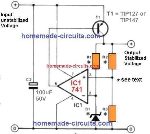
High Voltage, High Current DC Regulator Circuit - Homemade ...
Is an electric rat trap effective? I review one of the best. How does the electric rat trap work? These traps are powered by four 'C' batteries which the manufacturers say will kill about 50 rats. I've found it to be a lower number than that - probably around ten to twelve. The rat, enticed into the box by a yummy treat at the entrance and smeared on the back wall, steps on a metal plate.

Victor® - The Mouse Trap Company Since 1898
Victor Electronic Rat Trap M241 - The Home Depot The Victor Electronic Rat Trap is the ultimate in rodent control. It works by delivering a humane, high-voltage shock to effectively kill the invading rat. This powerful device is capable of killing up to 50 rats per set of fully charged batteries (4 C), making it a great value when you're dealing with a sizable infestation. It's also easy to use.

Electronic Rat Trap Circuit , Png Download - Electric Mouse ...
Where can I find circuit for electronic rat trap? - Page 1 -- Assuming you're referring to a rat trap that uses electricity to kill --Yeah, I think you should start by building some boost converters that operated at safe voltages (e.g. a boost convert from 5V USB up to 12 or 24V), and get lots of experience with that.Then you'll maybe (not really) have enough experience to safely work with 8000V, and you'll be knowledgeable enough to understand the ...

Humane Rat Trap Notifier - Hackster.io
High Voltage Pulse Capacitor Rat Trap - Blogger Victor Electronic Mouse Trap In Action With Motion Cameras Full Review Mouse Trap Mondays. Greensource. ... Electronic Pests Killing Lamp Circuit Diagram 6. Synchronized Stimulation And Continuous Insulin Sensing In A. Best Mouse Zapper Near Me And Get Free Shipping A229.

Figure 3 from Development and Implementation of a PIN-Diode ...
Simple Rat Repellent Circuit - Making Easy Circuits Nov 04, 2020 · This electronic rat repellent circuit really is easy as it simply works with a several unique variations of components. Therefore to suit your needs who may be presently studying, researching electronics, may make an effort to practice causes this circuit as it is regarded as less difficult for newbies.

Arduino Mouse Trap : 5 Steps (with Pictures) - Instructables
Mouse and Rat repellent circuit using astable multivibrator As Figure 1 in this circuit will have two monostable multivibrators. In frist set will consists of TR1 and TR2 are used to generate a low frequency by have C2, C3, R1-R4, LED and VR- 100K, which it is the frequencies generators to Collector of TR2. LED will is used for power on display of this project. And VR-100K will be adjustable of timing range. The low frequency will be sent to control the high frequency generator. Which consist of TR3 and TR4 and R5-R8, C5, C6 will be combine to increasing frequency rises up. Before send to piezo speaker next. In this the frequency generator will work according to the rhythm, The performance of low-frequency generator. We heard a sound out of the speakers at intervals.
SMART MOUSE TRAP
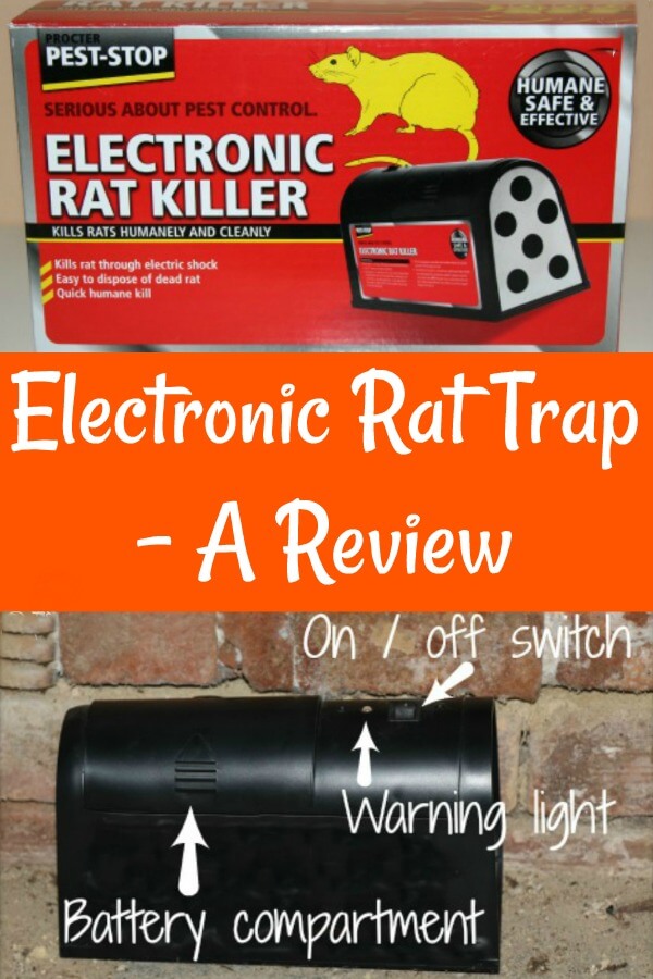
Is an electric rat trap effective? I review one of the best.

Building a better Rat trap 2 – Doktor Ross Sewage

Go Ahead, Connect an Inductor and Capacitor and See What ...

How to make Electric Mouse Trap/ Electric Mousetrap With Battery 12V

electronic mouse trap circuit - Basic_Circuit - Circuit ...

Best Snap Traps for Rats - Learn Key Features That Make Them ...
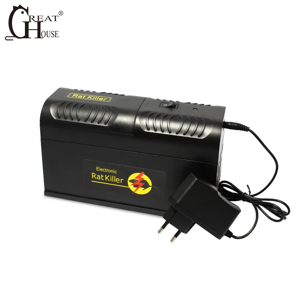
Gh-190 Electronic Rat Killer Rat Trap - Buy Rat Traps,Rat Trap,Rat Trap Product on Alibaba.com

Electronic Live Capture Mousetrap | Electronics, Capture, Diy ...

Electronic Live Capture Mousetrap
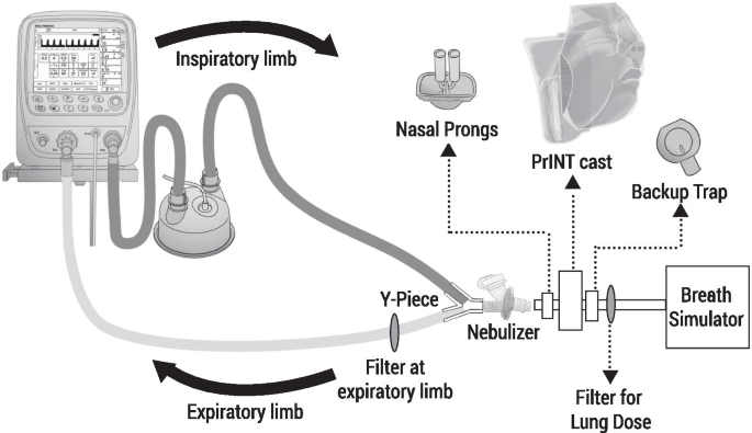
Aerosol drug delivery to spontaneously-breathing preterm ...
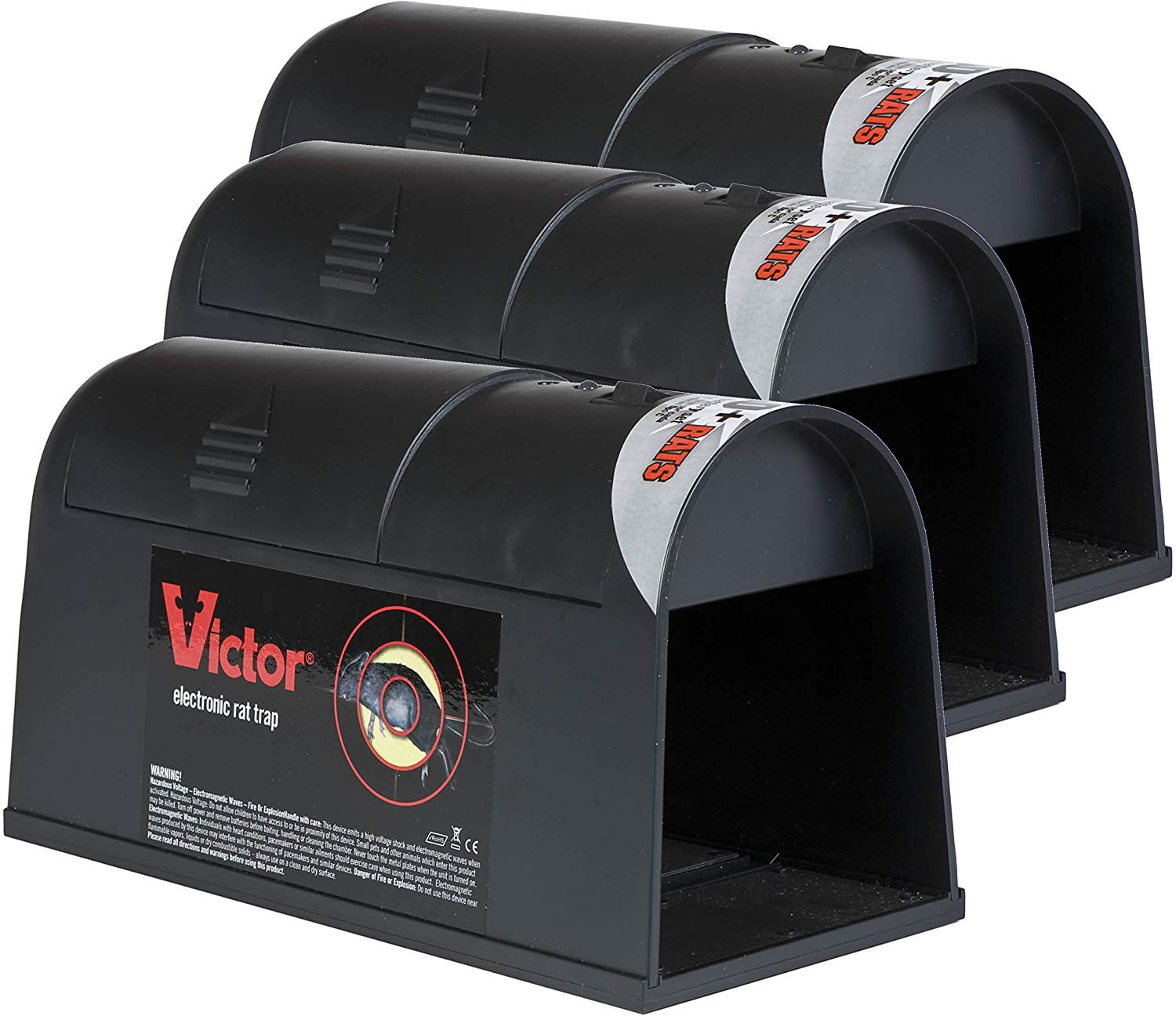
Victor M240 Electronic Rat Trap No Touch No See Reusable ...
Mouse Garbage High Resolution Stock Photography and Images ...
1st Rat Trap | Nghia Ho
Rat Trap
Electronic pests killing lamp circuit diagram 6 ...
Applied Sciences | Free Full-Text | Towards Bio-Hybrid Energy ...
Building a Better Naked-mole rat Trap MEMS 411- Senior Design ...

Finally caught a mouse that's been tormenting me | NeoGAF
Applied Sciences | Free Full-Text | Design and Implementation ...

A guide to kit for controlling rats, mice and squirrels ...

Design for a mains-powered rat zapper circuit | Electronics ...

Smart Rat Trap - Make:
Electronic Live Capture Mousetrap

Balance Valves High Resolution Stock Photography and Images ...

Where can I find circuit for electronic rat trap?

How To Make a High Voltage Mouse Trap / Electric Shock For ...
Project Title - Electronic Pest Repellent

How to make DIY Automatic Rat/Mouse Trapper at Home - STEMpedia


Comments
Post a Comment