41 temperature sensor circuit diagram
Simple temperature sensor diode 1N4148 - ElecCircuit.com Differential temperature controller circuit diagram. First, The diode sensor gets a forward-biased current. Then, there are the current flows through VR1, R1, R2, R3. We adjust VR1 to set the current, flows both diodes to be the same temperature. When both diodes get a different temperature. The voltage across them also are different. PDF Temperature Measurement Circuits for Embedded Applications faced to an amplifier circuit to provide a voltage which is proportional to temperature. Analog output silicon sensors are available that integrate the sensor and the signal conditioning circuit. Figure 1 shows a block diagram of a typical analog interface circuit. FIGURE 1: Block Diagram of an Analog Output Sensor. Author: Jim Lepkowski
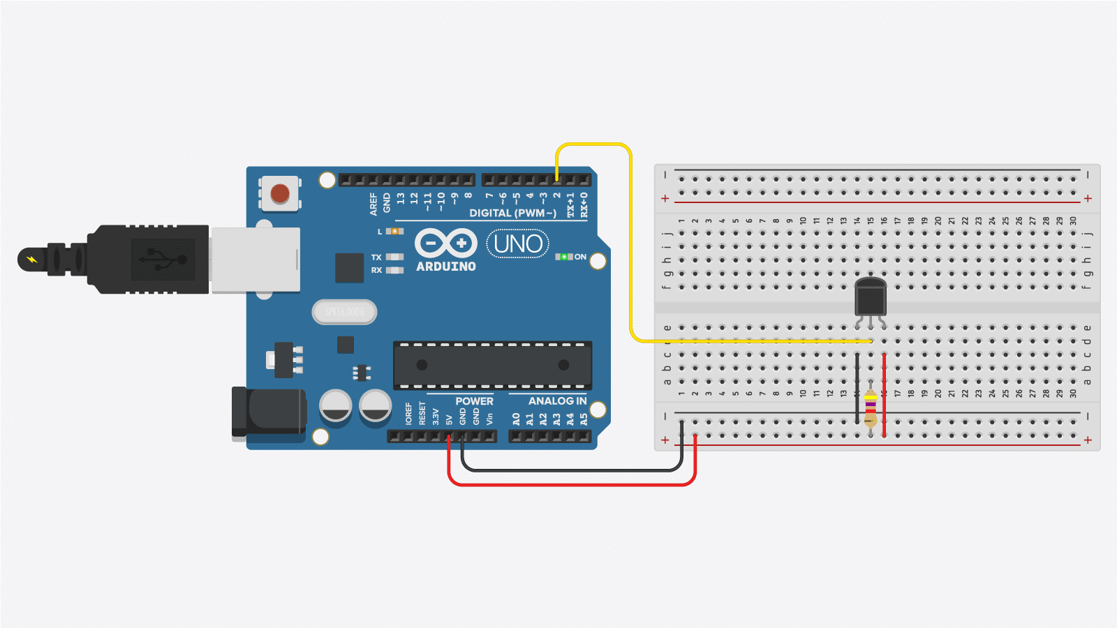
DS18B20 Temperature Sensor With Python (Raspberry Pi) 25.06.2017 · With your Raspberry Pi turned off, build the circuit as per this diagram. The DS18B20 is placed into the breadboard so that the flat side faces you. The black jumper cable goes from GND, which is the third pin down on the right column to the first pin of the DS18B20. The yellow jumper cable goes from the fourth pin down on the left column and is connected to …

Temperature sensor circuit diagram
PDF TEMPERATURE SENSOR - Maxim Integrated thermistors, local temperature sensor ICs, and remote thermal diode temperature sensor ICs. Thermocouples, RTDs, and thermistors are sensing elements that respond to temperature in a measurable way. They are normally connected to circuits that convert the sensor signal into a usable analog or digital value. The circuits are Temperature Sensor with 2-Wire Interface Schematic Circuit ... The temperature is given by the formula T = (f - 10000) / 38 where T is the temperature in °C and f the frequency in Hz. The frequency therefore ranges from 8.8 kHz (at -30 °C) to 15.7 kHz (at +150 °C). The output transistor of IC1 has its collector at pin 1 and its emitter at pin 2. Temperature Sensor : Circuit, Types, Advantages & Its ... Temperature Sensor Circuit The circuit diagram of the relay switch using the temperature sensor is shown below. Once the circuit gets the heat then the relay will trigger the load. Any voltage can be applied to this relay like 110V AC or 220V AC or DC appliance so that we can control it routinely on the preferred temperature.
Temperature sensor circuit diagram. Arduino - Temperature Sensor - Tutorialspoint The Temperature Sensor LM35 series are precision integrated-circuit temperature devices with an output voltage linearly proportional to the Centigrade temperature. The LM35 device has an advantage over linear temperature sensors calibrated in Kelvin, as the user is not required to subtract a large constant voltage from the output to obtain ... › light-sensor-circuitLight Sensor - Circuit Diagram, Working and Its Applications Jan 07, 2021 · Light Sensor Circuit Working Operation. The light sensor circuit is an electronic circuit designed using (light sensor) LDR, Darlington pair, relay, diode, and resistors which are connected as shown in the light sensor circuit diagram. A 230v AC supply is provided to the load (in this case, the load is represented with a lamp). Heat Sensor Circuit Diagram - engineersgarage.com Heat Sensor Circuit Diagram December 26, 2018 By Ashutosh Bhatt Heat sensor senses the heat present around the sensor. When temperature rises above the set value, it will indicate the presence with the help of glowing LED. This circuit can be used in kitchen or inside your PC. Electrical Symbols — Thermo | Electrical Symbols ... A thermocouple is an electrical device consisting of two different conductors forming electrical junctions at differing temperatures. A thermocouple produces a temperature-dependent voltage as a result of the thermoelectric effect, and this voltage can be interpreted to measure temperature. Thermocouples are a widely used type of temperature sensor. 26 libraries of the Electrical ...
6 Kinds of NTC Thermistor Temperature Measurement Circuit ... Ntc thermistor temperature measurement interface circuit diagram (6) Fig. 2 is an interface circuit for temperature measurement of thermistor sensor using in-phase amplifier circuit. The interface circuit uses a resistor to linearize the thermistor sensor, and the interface circuit has a voltage mode and a resistance mode. MLX90614 Infrared Temperature Sensor with Arduino, Circuit ... In the circuit diagram, you can clearly see the MLX90614 Non-Contact temperature Sensor connection with the Arduino remain exactly the same. As the MLX90614 and the SSD1306 Oled display Module both are I2C supported, so we can interface both the devices using only two pins the A4 and A5 pins. How to Build a LM35 Temperature Sensor Circuit Temperature Sensor Circuit Schematic. The temperature sensor circuit we will build is shown below: This translates into the circuit schematic: So you circuit connections are: Pin 1 of the LM35 goes into +5V of the arduino. Pin 2 of the LM35 goes into analog pin A0 of the arduino. Pin 3 of the LM35 goes into ground (GND) of the arduino. Temperature Indicator Circuit - ElectroSchematics.com The multimeter is a measurement device most used by engineers and we use it in this temperature indicator circuit schematic. The temperature sensor is LM335 wich has a linear characteristic of 10mV / K . In the production process this electronic device is calibrated so can provide 2.73V at 0°C.
axleaddict.com › auto-repair › Intake-AirTesting the Intake Air Temperature Sensor - AxleAddict Use the diagram that comes in your vehicle repair manual to check the circuit and identify the wires for the IAT sensor in your car, if necessary. Photo courtesy of Alexey A. Shabelnikov, UA, Kiev on Wikimedia. Arduino - Temperature Sensor | Arduino Tutorial Learn how to use temperature sensor with Arduino, how to connect DS18B20 temperature sensor to Arduino, how to program Arduino step by step. The detail instruction, code, wiring diagram, video tutorial, line-by-line code explanation are provided to help you quickly get started with Arduino. Find this and other Arduino tutorials on ArduinoGetStarted.com. Humidity Sensor - Simple Circuit Diagram Humidity is the amount of water vapor in the air, expressed as a percentage of the maximum amount that the air could hold at the given temperature. To build a humidity sensor can be difficult because of their wide dynamic range and sensor's drive requirement. But we can build the humidity sensor with reasonable accuracy within the chosen ... lm35 temperature sensor working principle circuit diagram ... The circuit diagram of the Arduino LM35 Temperature Sensor is easy. Analog pin A0 used as input of the Arduino. The output pin of LM35 is connected to Analog Input A0. Join LM35 output pin to it. Apply 5 volts to Vcc pin of LM35 and ground pin. Working:
Digital Temperature Sensor Circuit – Dharmen Bisen
Temperature Measurement using LM35 and ... - Circuit Digest 26.06.2015 · This circuit is developed using “LM35”, a linear voltage sensor. Temperature is usually measured in “Centigrade” or “Faraheite”. “LM35” sensor provides output based on scale of centigrade. LM35 is three pin transistor like device. It has VCC, GND and OUTPUT. This sensor provides variable voltage at the output based on temperature.
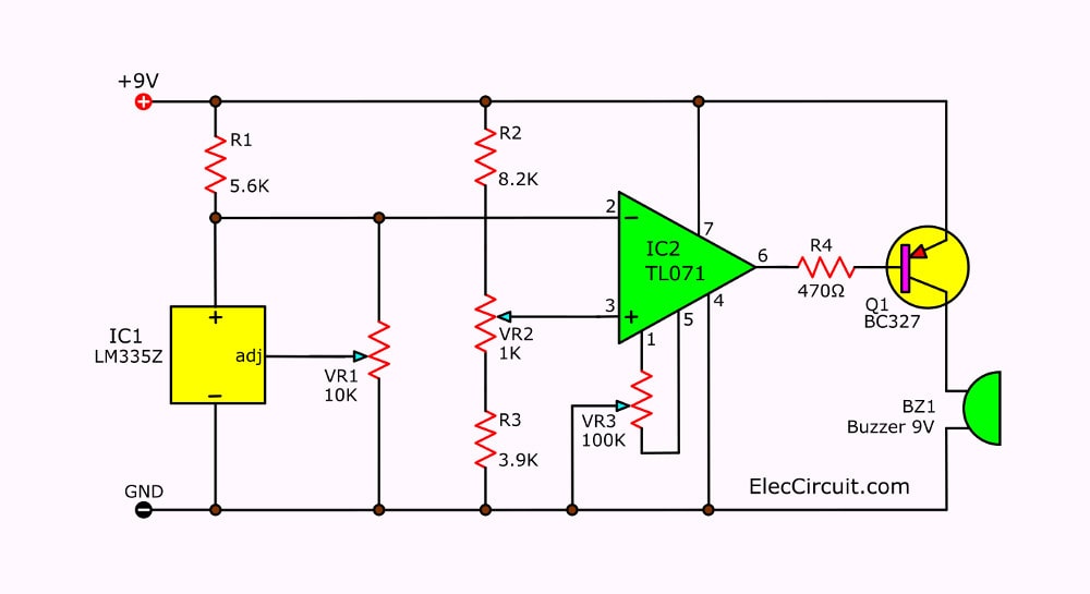
3 Temperature detector circuit with buzzer alarm ...
Temperature Sensor Circuit using Thermistor Temperature Sensor Circuit using Thermistor. In this tutorial, we are making a project of a Simple temperature sensor circuit. This circuit activates an LED when it senses or receives heat so you can also call this circuit a heat sensor circuit. Apart from its uses, If you are a beginner who just wants to make an easy and interesting project ...

Circuit Diagram of the temperature sensor circuit | Download ...
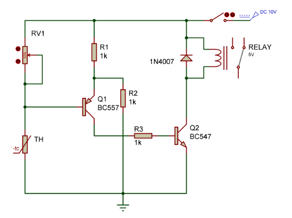
Wireless Temperature Sensor with Thermistor - Circuits DIY Circuit Diagram Working Explanation In the first stage of this circuit that is a temperature sensor circuit is built around two 2N4401 transistors which are working as switches. A 10K thermistor is used to sense the heat. To adjust the level of heat on which you want the circuit to activate we have used a variable resistor of 20K.

Arduino Room Temperature Monitor
Circuit Diagram of the temperature sensor circuit ... Download scientific diagram | Circuit Diagram of the temperature sensor circuit from publication: Real-Time Wireless Network of Mobile Sensor Nodes Based on ZigBee Protocol: Design and ...

Building a Temperature Sensor | Jaycon Systems
Pt100 3 Wire Temperature Sensor Circuit Diagram - U Wiring Pt100 Temperature Sensor Wiring Diagram wiring diagram is a simplified pleasing pictorial representation of an electrical circuitIt shows the components of the circuit as simplified shapes and the talent and signal associates surrounded by the devices. Three-wire ohm platinum RTD sensors PTalpha.

Temperature Sensor Types for Temperature Measurement
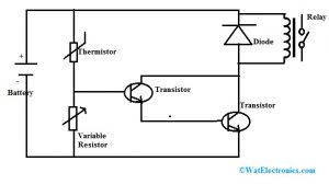
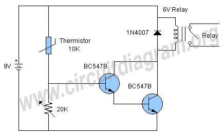
Temperature Sensor Circuit - Circuit Diagram Temperature Sensor Circuit | Circuit Diagram The schematic shown here is a project of a simple temperature sensor circuit or we can also say it a heat sensor circuit, which will activate an LED when receive heat. The circuit is easy to make and using only few components. The two BC547B transistors are connected as a darlington pair to increase
Temperature Sensor for Arduino applied for COVID 19 - Hackster.io
Simple Heat Sensor Circuit Simple Heat Sensor Circuit. We have previously built the Fire Alarm using Thermistor and Fire Alarm System using AVR Microcontroller. Today we are building very simple Temperature Sensor Circuit or Heat Sensor Circuit. This circuit uses very few and basic components which can be easily available, anyone can build it right away.

Temperature Sensor Circuit..Simple Heat Sensor Science Project..
Digital Temperature Controller | Full Circuit Diagram With ... Fig. 2 shows circuit diagram of the digital temperature controller. The circuit is built around microcontroller PIC16F877A (IC1), precision thermocouple amplifier AD8495 (IC2), K-type thermocouple (connected at CON3), 16×2 LCD (LCD1), single-changeover relay (RL1) and a few common components. Sensor selection.
Room temperature sensor, NTC8K, flush-mounted, cover 50x50mm ...
Temperature sensor circuit diagrams Fan Controller. This circuit controls very accurately a fan of any size. Just adjust the associated resistors for a different type like the R6 resistor of 100 ohm, 2 watt type and you're all set. The above circuit diagram is for a small 12 volt fan, the size and type determined by the user.
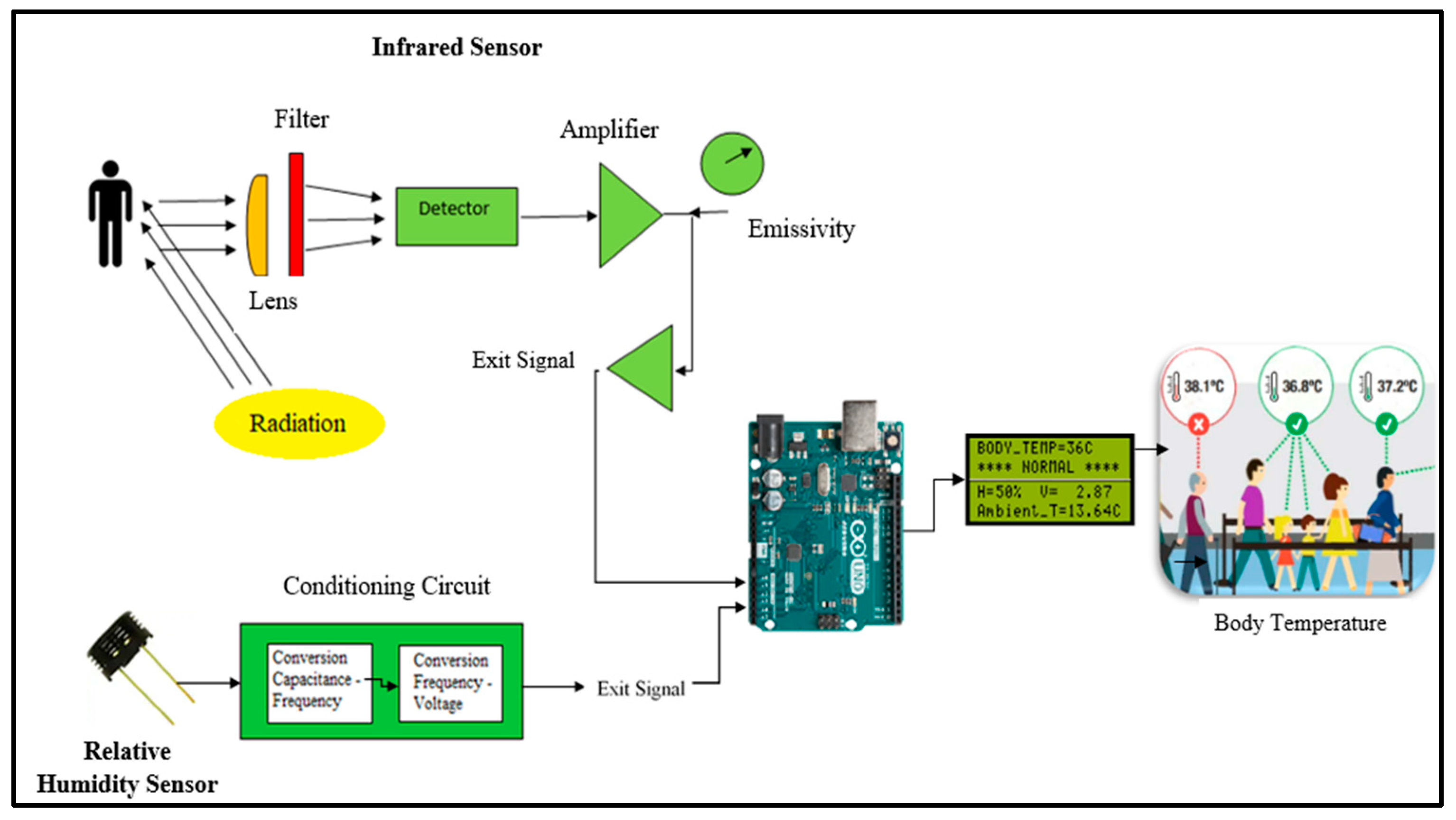
Electronics | Free Full-Text | A Non-Contact Integrated Body ...
Temperature sensing with NTC circuit (Rev. A) This temperature sensing circuit uses a resistor in series with a negative-temperature-coefficient (NTC) thermistor to form a voltage divider, which has the effect of producing an output voltage that is linear over temperature. The circuit uses an op amp in a non-inverting configuration with inverting reference to offset and
Temperature Sensor : Circuit, Types, Advantages & Its ...
Temperature sensor circuit. | Download Scientific Diagram Download scientific diagram | Temperature sensor circuit. from publication: Water Cerenkov muon detector near the Angra-II reactor core: the hardware | We report the installation, near the Angra ...
How to Build a Temperature Sensor Circuit
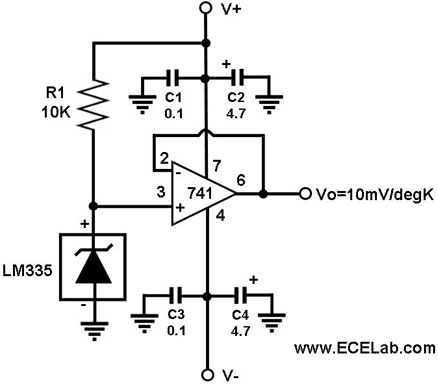
Temperature Sensor - Simple Circuit Diagram Resistance temperature sensor (RTD, resistive temperature device) comes in NTC (negative temperature coefficient) and PTC (positive temperature coefficient) forms. A schematic diagram below show a signal conditioner circuit for such thermometer. This sensor conditioning circuit works in current mode (current loop) and the amplifier inside gives ...
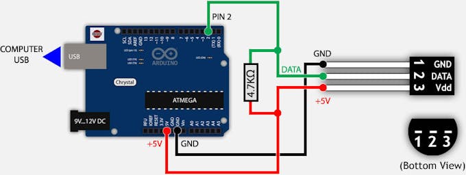
DS18B20 (Digital Temperature Sensor) and Arduino - Arduino ...
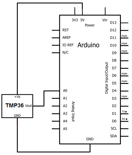
TMP36 Temperature Sensor Arduino Tutorial (2 Examples) Wiring - Connecting TMP36 temperature sensor to Arduino. Connecting a TMP36 to the Arduino is very easy as you only need to connect 3 pins. Start by connecting the +V S pin to the 5 V output of the Arduino and the GND pin to the ground. If you are using a 3.3 V Arduino, simply connect +V S to 3.3 V instead.. Next, connect the middle pin (V OUT) to any of the analog inputs of the Arduino.

Arduino - Humidity Sensor - Arduino Project Hub
1, 2, & 3 Wire Coolant Temperature Sensor Wiring Diagram The wiring diagram of the coolant temperature sensor is based on year, make, and model. The color of the engine coolant temperature sensor varies and is color-coded according to the make and model. Below are the 1, 2, and 3 wire engine coolant temperature sensor wiring diagrams. I . Single Wire Coolant Temperature Sensor Wiring Diagram

Signal conditioning circuit for Pt100 temperature sensor ...
circuitdigest.com › electronic-circuits › pir-sensorPIR Sensor Based Motion Detector/Sensor Circuit - Circuit Digest May 22, 2015 · Pyroelectric sensor is covered by a plastic cap, which has array of many Fresnel Lens inside. These lenses are curved in such a manner so that sensor can cover a wide range. We have built a very simple Motion detector circuit here. We are using a HC-SR501 PIR Sensor, an LED (which will glow whenever there is a motion infront of the sensor) and ...
Low Noise CMOS Temperature Sensor with On-Chip Digital ...
› arduino-soil-moisture-sensorArduino&Soil Moisture Sensor-Interfacing Tutorial-Circuit ... Oct 31, 2020 · When the sensor value will be greater than the threshold value, then the digital pin will give us 5V and the LED on the sensor will light up and when the sensor value will be less than this threshold value, then the digital pin will give us 0V and the light will go down. Circuit Diagram

Circuit diagram of the temperature sensor with ADC ...
Humidity and Temperature Sensor Circuit diagram Using ... The circuit is a simple circuit design that has an analog humidity and temperature sensor, Arduino Uno, and a 16x2 LCD module. The sensor can operate with a supply range from 2.4V to 5.5V. The RH pin in the sensor is for relative humidity signal while the T pin is for the temperature signal.
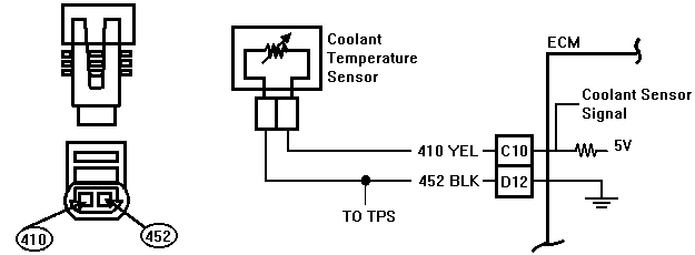
Code 15 - Coolant Temperature Sensor Circuit
Temperature Sensor : Circuit, Types, Advantages & Its ... Temperature Sensor Circuit The circuit diagram of the relay switch using the temperature sensor is shown below. Once the circuit gets the heat then the relay will trigger the load. Any voltage can be applied to this relay like 110V AC or 220V AC or DC appliance so that we can control it routinely on the preferred temperature.
temperature sensor PT100 4wire - CircuitLab
Temperature Sensor with 2-Wire Interface Schematic Circuit ... The temperature is given by the formula T = (f - 10000) / 38 where T is the temperature in °C and f the frequency in Hz. The frequency therefore ranges from 8.8 kHz (at -30 °C) to 15.7 kHz (at +150 °C). The output transistor of IC1 has its collector at pin 1 and its emitter at pin 2.

SPICE models for platinum temperature sensors: Simulating ...
PDF TEMPERATURE SENSOR - Maxim Integrated thermistors, local temperature sensor ICs, and remote thermal diode temperature sensor ICs. Thermocouples, RTDs, and thermistors are sensing elements that respond to temperature in a measurable way. They are normally connected to circuits that convert the sensor signal into a usable analog or digital value. The circuits are
IR-Link Temperature Sensor Allows Isolation of the Temp Sensor
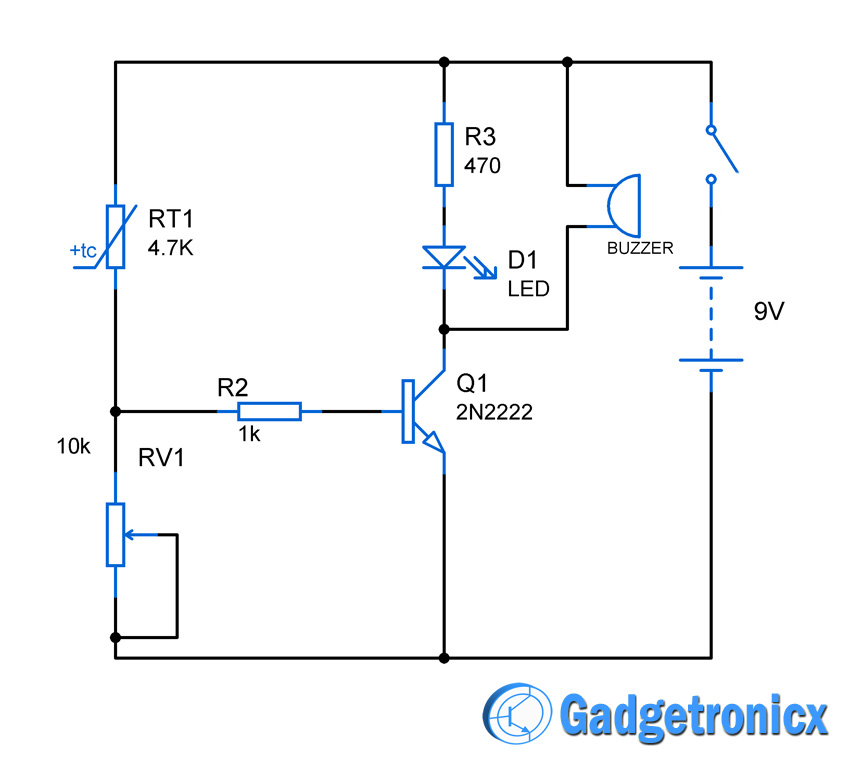
Heat sensor circuit Diagram - Gadgetronicx

High / Over Temperature Sensor Alarm Circuit Diagram | Sensor ...
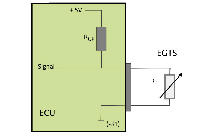
Checking the exhaust gas temperature sensor | HELLA

How to turn on LED with temperature sensor - Electrical ...
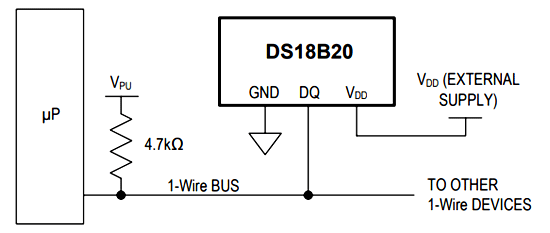
DS18B20 Temperature Sensor Pinout, Specifications ...
Temperature Sensor Relay Switch Circuit | Circuit Diagram
Temperature Relay controller switch Circuit - Gadgetronicx

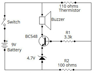
Heat / Temperature Sensor Alarm | Circuit Diagram
Simple Heat Sensor or Temperature Sensor Circuit Diagram
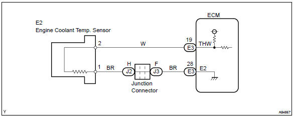
Toyota Corolla Repair Manual: Circuit description - Engine ...
Heat Sensor Circuit And Its Working Principle

Temperature Sensor Circuit using Thermistor
Results page 20, about 'NTC temperature thermistor ...
DS18B20 Temperature Sensor Arduino Tutorial (4 Examples)

Circuit of temperature and humidity sensor | Download ...

Cold Sensor Circuit
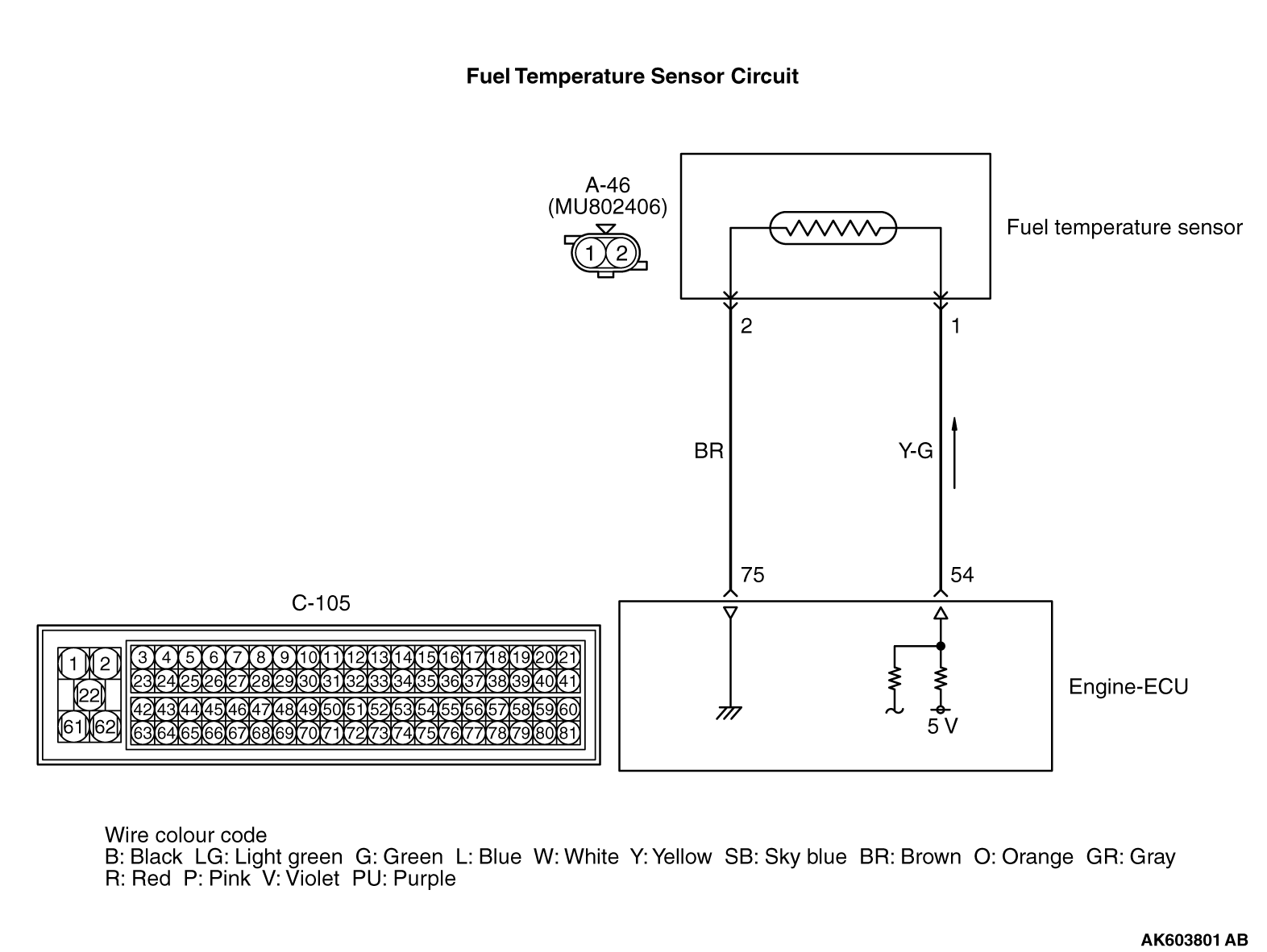
Code No. P0183: Fuel Temperature Sensor Circuit High Input
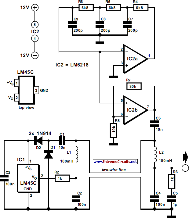
Two-Wire Temperature Sensor Circuit Diagram

Digital Temperature Sensors | Analog Devices
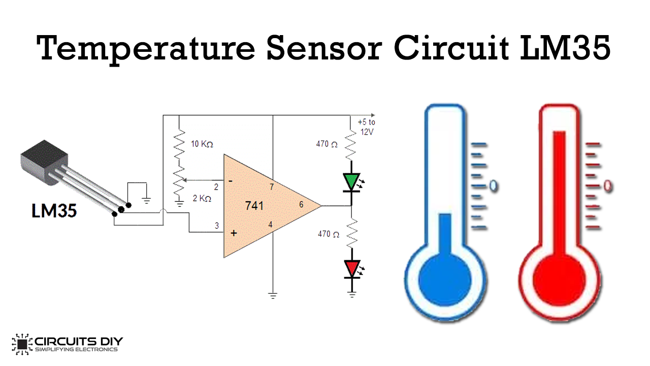
Simple Temperature Sensor Circuit using LM35 IC


Comments
Post a Comment