41 john deere 5525 wiring diagram
Search for your specific John Deere Tractor Technical Manual PDF by typing the model in the search box on the right side of the page. About Your John Deere. John Deere & Company was founded in 1837. It has grown from a blacksmith shop with only one person to a group company that now sells in more than 160 countries around the world and employs ... 1 John Tractor 5525 Wiring Diagram Free PDF ebook Download: John Tractor 5525 Wiring Diagram Download or Read Online ebook john deere tractor 5525 wiring diagram in PDF Format From The Best User Guide Database John Service Advisor 4.0 Agriculture workshop service manual, repair manual, electrical wiring diagram, hydraulic diagram, diagnostic, assembly and disassembly engine, transmission..
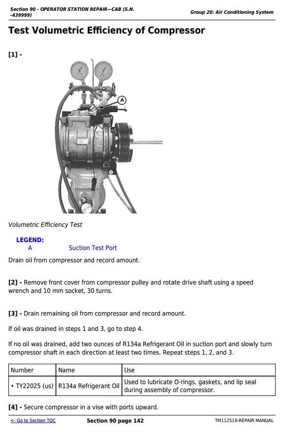
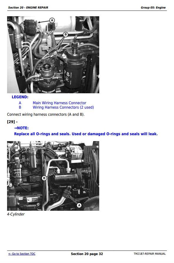
Description. Factory Technical Repair Manual For John Deere TM2187 5225 5325 5425 5525 5625 5603 Tractors. Tons of illustrations, instructions, diagrams for step by step remove and install, assembly and disassembly, service, inspection, repair, troubleshooting, tune-ups. Format: PDF.

John deere 5525 wiring diagram
John Deere 5525 Wiring Diagram Download. A wiring diagram is a schematic type that uses abstract illustrated symbols to show all of the components of a system. Wiring diagrams are made up of two things: symbols that represent the components of a circuit, and lines that represent the connections between them. John Deere 5525 Wiring Diagram 14.09.2018 14.09.2018 5 Comments on John Deere 5525 Wiring Diagram 1-Warning Light Power Relay 2-Fuse F1, Amp: Ignition Switch 3-Fuse F2, Amp: Warning Light Power Relay, Left Turn Relay and Right Turn Relay. Complete Diagnosis & Tests Technical Manual with electrical wiring diagrams for John Deere Tractors 5225, 5325, 5425, 5525, 5603, 5625, with all the service information to maintain, diagnose, service, rebuild like professional mechanics.. John Deere Tractors 5225, 5325, 5425, 5525, 5625, 5603 workshop technical Diagnosis & Tests technical manual includes: * Numbered table of contents easy to ...
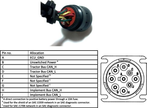
John deere 5525 wiring diagram. John Deere service and support onscreen help. 7-Pin outlet (A) is used to connect lights, turn signals, and remote electrical equipment on trailers or implements. Tractors equipped with front hitch have a 7-Pin outlet (A) located on front of tractor. Always use auxiliary light on towed implement when tractor signals and other lights are obscured. John Deere 5525 Wiring Diagram. Print the wiring diagram off in addition to use highlighters to be able to trace the signal. When you use your finger or stick to the circuit with your eyes, it may be easy to mistrace the circuit. 1 trick that We use is to print a similar wiring picture off twice. John Deere Tractors 5225, 5325, 5425, 5525, 5603, 5625 workshop technical manual (repair) includes: * Numbered table of contents easy to use so that you can find the information you need fast. * Detailed sub-steps expand on repair procedure information * Numbered instructions guide you through every repair procedure step by step. John Deere Parts Diagrams, John Deere 5525 TRACTOR (HI-CROP) -PC9402. "VEGGIE" WHEELS,MFWD: WHEELS. 1127 ROCKER ARM COVER: ENGINE 4045TLV56. 1202 OIL FILL: ENGINE 4045TLV56. 1302 CRANKSHAFT PULLEY: ENGINE 4045TLV56. 1462 FLYWHEEL HOUSING: ENGINE 4045TLV56. 1587 FLYWHEEL: ENGINE 4045TLV56. 16K4 FUEL INJECTION PUMP: ENGINE 4045TLV56.
Complete Diagnosis & Tests Technical Manual with electrical wiring diagrams for John Deere Tractors 5225, 5325, 5425, 5525, 5603, 5625, with all the service information to maintain, diagnose, service, rebuild like professional mechanics.. John Deere Tractors 5225, 5325, 5425, 5525, 5625, 5603 workshop technical Diagnosis & Tests technical manual includes: * Numbered table of contents easy to ... John Deere 5525 Wiring Diagram 14.09.2018 14.09.2018 5 Comments on John Deere 5525 Wiring Diagram 1-Warning Light Power Relay 2-Fuse F1, Amp: Ignition Switch 3-Fuse F2, Amp: Warning Light Power Relay, Left Turn Relay and Right Turn Relay. John Deere 5525 Wiring Diagram Download. A wiring diagram is a schematic type that uses abstract illustrated symbols to show all of the components of a system. Wiring diagrams are made up of two things: symbols that represent the components of a circuit, and lines that represent the connections between them.
John Deere Radios Speakers Radio Harness
2

Alpine Cde 123 Wiring Diagram Auto Electrical Wiring Diagram
John Deere 3100 3200 3300 3400 Tractor Service Manual Tm4525

Oem Ignition System Kawasaki Motorcycle Ex 250 F Ninja 250r F15 F19 Ninja 250r 2002 Goparts

I Need The Electrical Schematic For The Light System On A 4055 Deere Tractor
John Deere 5425 Tractor Pc9402 Fuel Injection Pump Wiring Harness Switch Cold Start Advance Engine 4045tlv53 4045tlv54

I Need The Electrical Schematic For The Light System On A 4055 Deere Tractor
1
Mtd Ca326hd 31ah54km897 2017 Parts Diagram For Chute Control

Jd 5225 Power Reverser Not Working Tractor Won T Move My Tractor Forum

Looking For A Hydraulic Diagram On A Deere 3130 Hydraulic Pressure And And Implement Lift Adjustment Lift Is Operating

Where Can I Find A Wiring Diagram On Line Fixya

John Deere 5225 5325 5425 5525 5625 5603 Diagnostic Technical Manual Tractors Tm2197 Erepairinfo Com

John Deere Tractor 5525 Wiring Diagram Pdf Free Download

John Deere 5225 5325 5425 5525 5625 5603 Diagnostic Technical Manual Tractors Tm2197 Erepairinfo Com
John Deere 5225 5325 5425 5525 5625 5603 Diagnostic Technical Manual Tractors Youfixthis

John Deere 5083e 5093e 5101e And Limited Models Tractors Repair Manua Manual4you
Tm112519 John Deere Tractors 5083e 5093e 5101e And Limited Models Service Repair Manual Deere Technical Manuals

5525 Tractor Wiring Harness Console Powrreverser Transmission Isolated Open Operator Station Epc John Deere Ag Cce Online Avs Parts
John Deere Tractors 5225 5325 5425 5525 5625 5603 Service Repair Technical Manual Tm2187 Truck Service Manual Store

John Deere Tractor 5525 Wiring Diagram Pdf Free Download
3

Pin On John Deere Manuals

John Deere 5103 5103s And 5203 Tractors Technical Repair Manual Tm20 Manual4you

Cab Glass Left Hand Door Fits John Deere 6115d 5725 5320 6140d 5075m 5520 5325 6130d 5220 6403 6100d 5420 6603 5225 5425 5625 5085m 4630 5603 5525

My Deer 855 Will Not Start Battery Is New All Wires Are Fine I Did Notice That My Pedals To Go Forward And Reverse
John Deere 5083e 5093e 5101e Tractor Service Manual Farm And Construction Manuals
Pto Switch Electrical Replacement Parts Genuine Parts John Deere Products Johndeerestore
User Manual Tractor Hacking

John Deere Fuse Panel Problem Youtube

John Deere Service Advisor 4 0 2011 Cce Commercial And Comsumer Equipment
John Deere 5055e 5045e 5065e 5075e Hydraulics And Hitch
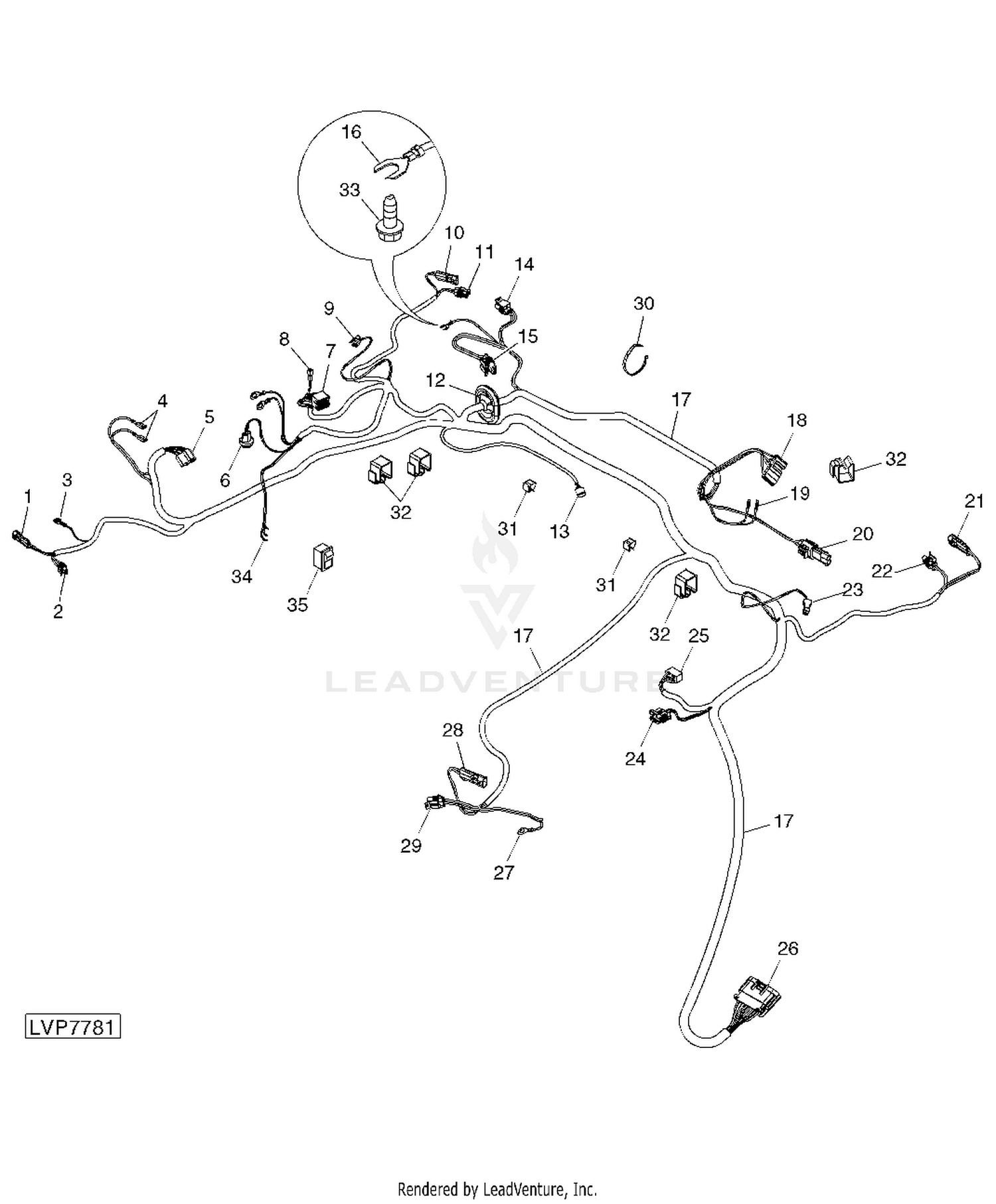
John Deere 5525 Tractors John Deere 5525 Tractor Hi Crop Pc10868 Wiring Harness Roof Cab Electrical Wiring Harnesses Tractor
Need Wiring Patter For Mfwd Sensor On A 3320 Or John Deere Wire Planning Sucks Tractorbynet

John Deere 5225 5325 5425 5525 5625 5603 Diagnostic Technical Manual Tractors Tm2197 Erepairinfo Com

9l5574 Brakesaver Manual Control Group Factory Installation For Use With 9l5561 Arrangement For Up To 425 H P Of Retarding At Flywheel 1s3998 Valve Parts Are Shown On Page 74 1693 Avspare Com

Battery And Cables Tractor John Deere 5525 Tractor 5525 Tractor Electrical Components Tractor Battery And Cables 777parts
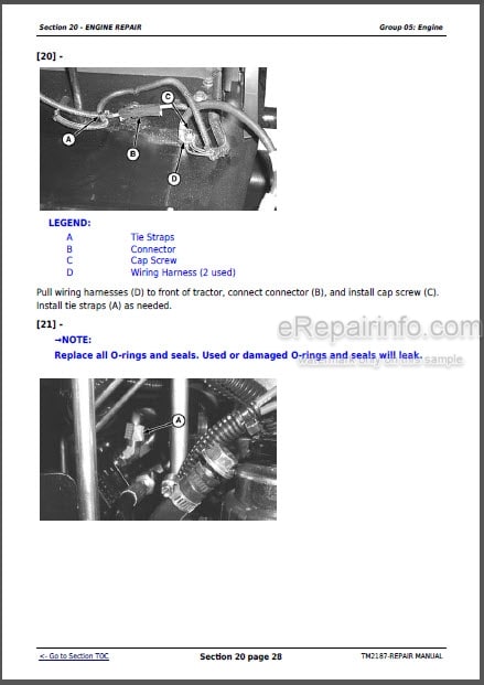
John Deere 5225 5325 5425 5525 5625 5603 Repair Manual Tractors Tm2187 Erepairinfo Com
Pto Switch Electrical Replacement Parts Genuine Parts John Deere Products Johndeerestore
Abbyy Finereader Pdf For Mac Single Seat Licenses Screenshots Academic Center Der Softwareshop Fur Forschung Und Lehre


Comments
Post a Comment