42 phasor diagram generator
Jan 1, 2021 — Voltage drop due to armature reaction. ... From the above voltage equation, let us draw the phasor diagram of a synchronous generator operating at ... a. Convert the per unit generator reactance to the step-up transformer base. b. The system is supplying 750 MW at 345 kV and 0.90 power factor leading to the system at the transformer terminals. Draw a phasor diagram for this condition, using the transformer high-side voltage as the reference phasor.
From the phasor diagram, we get R Thus the average power dissipated per cycle in a capacitor is zero. Question 19. The circuit arrangement as shown in the diagram shows that when an a.c. passes through the coil A, the current starts flowing in the coil B. (i) State the underlying principle involved.

Phasor diagram generator
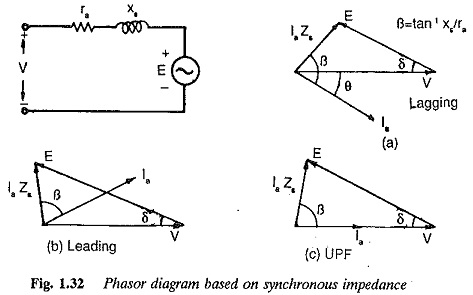
The value of resistance R shall be such that it will limit the fault current to the full rating of the largest generator or transformer. (a) Circuit Diagram (b) Phasor Diagram. Fig. 1: Resistance Grounding \[R=\frac{V_{L}}{\sqrt{3}I}\] where, R = Resistance. V L = Line volume, I = Full-load current of largest machine UNIT I SYNCHRONOUS GENERATOR. Constructional details -Types of rotors -winding factors- emf equation -Synchronous reactance -Armature reaction -Phasor diagrams of non salient pole synchronous generator connected to infinite bus-Synchronizing and parallel operation -Synchronizing torque -Change of excitation and mechanical input- Voltage regulation -EMF, MMF, ZPF and A.S.A methods -steady ... Changing a Reactive Load. Start by assuming that the generator is connected to a lagging power factor load. In this case, the simplified phasor diagram is as ...
Phasor diagram generator. For example, let us consider the phasor E, as shown in the below diagram. From the endpoint of the phasor, draw a horizontal line and vertical line towards the X-axis and Y-axis respectively. Now, the phasor E is said to have horizontal component 'a' and vertical component 'b'. Thus in rectangular form, the phasor can be mathematically ... Phasor Diagram Creator. Log InorSign Up.. Enter values for voltage in V, and phase in P. Enter values for voltage in V, and phase in P. The value of resistance required for grounding purposes increases with the increase in operating voltage in order to limit the short circuit current during an earth fault. The resistance grounded system with earth fault at point F in phase B is shown above and its phasor diagram is shown in the below figure. Aug 29, 2021 — Phasor Diagram of a Synchronous Generator · Ef which denotes excitation voltage · Vt which denotes terminal voltage · Ia which denotes the armature ...
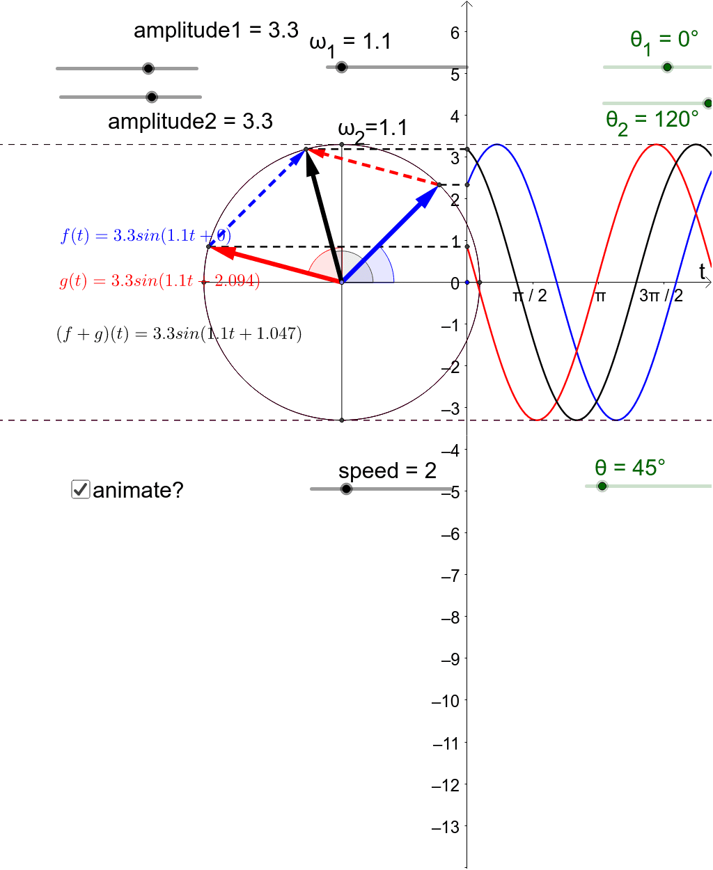
(4) The capacitor absorbs the back emf of the motor and keeps healthy the power circuit. When the power supply is suddenly off, the motor does not stop immediately, in this case, the motor act as a generator and produces the reverse voltage. Double Capacitor Motor Connection Electric Motor Capacitor Wiring Diagram - Database. Phasor Diagram and Phasor Addition. Phasor Diagram is a graphical representation of the relation between two or more alternating quantities in terms of magnitude and direction. In other words, it depicts the phase relationship between two or more sinusoidal waveforms having the same frequency. Phasor is a straight line with an arrow at one end ... A synchronous generator is supplying zero power factor (i)lagging and (ii) leading current. Show that the terminal voltage Vt and theexcitation emf Ef are in phase. In a synchronous motor drawing leading current at pf = cosi, draw the phasor diagram. Find therefrom the phase and magnituderelationships between Vt and Ef . Sep 30, 2021 — Equivalent Circuit and Phasor Diagram of Synchronous Generator or Alternator - The equivalent circuit of an alternator or synchronous ...
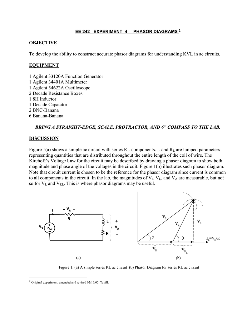
The stator winding has a synchronous reactance of 5Ω/ph and negligible resistance. The distribution factor for the statorwinding is 0.96. Calculate the terminal voltage when three non-inductiveresistors of 10 Ω/ph, are connected in star across the terminals. Sketchthe phasor diagram for one phase. A phasor diagram shows the relationship between voltages and currents. One such diagram is shown in Fig. 8.10 for a non-salient pole synchronous generator. by S Kudarauskas · 2007 · Cited by 2 — Phasor diagram for the salient pole synchronous generator can be constructed from the following equation. (that is, finding the terminal voltage U by ...4 pages phasor diagram of induction motor Posted on September 21, 2021 September 21, 2021 by Ranen Sen In Induction machine both the stator and rotor winding carry current and produce flux due to which the resultant air gap flux is obtained by sum of the flux of the 2 winding and this resultant flux is responsible for inducing an e.m.f in stator as ...
Resistance Grounding - Working, Phasor Diagram & Advantages November 26, 2021 The system in which the neutral point is grounded through a current limiting device (resistor) is known as a resistance grounded system and the grounding is referred to as resistance grounding.
The nucleus of fluorine has 9 protons. 11 AC Generator 07 Alternating Current 18 Topics Phasor Diagram Solution 12. 1. Build yFiles apps in seconds with this ETL tool. Bohr diagrams show electrons orbiting the nucleus of an atom somewhat like planets orbit around the sun. Find more Chemistry widgets in Wolfram|Alpha. Atomic structure atoms have ...
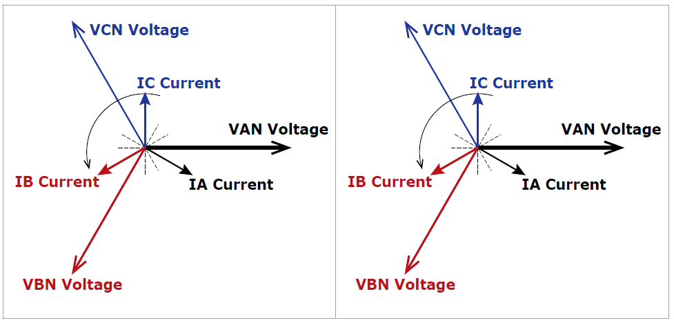
However, the relative phase angle between each pair of lines (1 to 2, 2 to 3, and 3 to 1) will still be −120°. A phasor diagram for a wye configuration, in which V ab represents a line voltage and V an represents a phase voltage. Voltages are balanced as: V ab = (1∠α − 1∠α + 120°) √ 3 V ∠α + 30°. 3 Phase Rotation Diagram
A wiring diagram is a simplified conventional photographic depiction of an electric circuit. Typical automatic transfer switch diagrams technical information. The ats is connected to utility mains source the ats is connected to utility mains source 1 and the generator source 2 with utility mains as the preferred source.
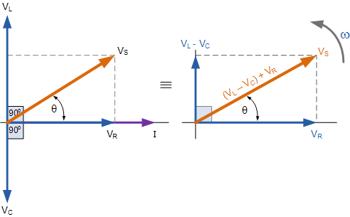
Steps to draw the Phasor Diagram of the RLC Series Circuit. Take current I as the reference as shown in the figure above; The voltage across the inductor L that is V L is drawn leads the current I by a 90-degree angle.; The voltage across the capacitor c that is V c is drawn lagging the current I by a 90-degree angle because in capacitive load ...
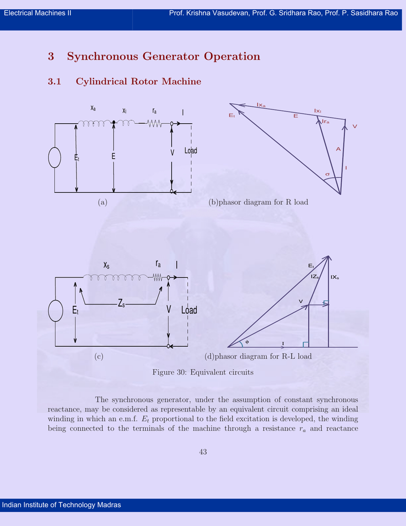
Blog Article Equivalent Circuit Model And Phasor Diagram Of A Synchronous Motor In Electrical Machines Uploaded In Lecturenotes Net Lecturenotes Net
5.Alternator with load and phasor diagram 00:10:59; 6. Voltage regulations ... (BE) appearing students, for securing good results. The course tries to cover all the basics of Three Phase Synchronous Generator, Synchronous Motor and Fractional Kilowatt Motor with solution of most frequently asked questions in final exam of BE with fundamental ...
Basics of creating circuit diagrams and printed circuit boards. Student knows the basics cla creating charts phasor. Paul Horowitz, Winfield Hill. Electromagnetic induction — induction effect, self-inductance, mutual inductance. Fundamentals of Electrotechnics and Electronics. Thyristor — types, properties, elektrotechinka. Power in AC circuit.
Parallel rc circuit phasor diagram analysis resistor capacitor circuits series impedance sine wave ppt solved example circuitant lecture 8 sinusoidal response of complex and l r time driving an laplace transform in simulating matt lacey objectives analyze a rl using diffeial equation modeling chapter 10 isu ee c y 18 capacitive topics solving ...
Oct 6, 2019 — As the output of the synchronous generator is alternating current, so it can easily be explained by the phasor diagrams. If we draw the output ...
Turn the main breaker ON. When the schematic is also a wiring diagram it is easier to understand the route a wire takes. How to Connect a Portable Generator to the Home Supply 4 Methods. Check the load center wiring diagram for confirmation the MBK200 is the equivalent to the EQ9685. Just connect the outgoing Neutral and Live wires to the UPS.
The generator field rheostat is kept at maximum resistance position. PROCEDURE OPEN CIRCUIT CHARACTERISTICS:- The connections are made as per the circuit diagram. ... phasor diagrams. UNIT-II ...
Stack Exchange network consists of 178 Q&A communities including Stack Overflow, the largest, most trusted online community for developers to learn, share their knowledge, and build their careers.. Visit Stack Exchange
12+ Basic Electrical Diagram. However, when polarity is a critical issue, it will be. Electrical symbols and electronic circuit symbols are used for drawing schematic diagram. Emf generation, average and effective values of sinusoids, j operations, complex representation of impedances, phasor diagrams, power factor.
There are 3 Circuits below. In this articles we discuss in detail. Pwm Vezerlo Speed Motor 12v By Tl494 Motor Speed Circuit Diagram Free Energy Generator Buy Now from Market-Leading Community with 430000 Engineers Online. Tl494cn circuit diagram. Buy Now from Market-Leading Community with 430000 Engineers Online. The winding particulars for the same. The uncommitted […]
Jun 9, 2016 — Cell B4: Enter in desired power factor · Cells B7-B17: Enter in any harmonic percentages · Cell B19: Enter power flow direction (+/-) · Cells Y2-Y3 ...
Working principle , Voltage build up in an induction generator 00:28:17; 9.Power stage diagram of induction generator ... Alternator with load and phasor diagram 00:10:59; 6. Voltage regulations ...
Changing a Reactive Load. Start by assuming that the generator is connected to a lagging power factor load. In this case, the simplified phasor diagram is as ...
UNIT I SYNCHRONOUS GENERATOR. Constructional details -Types of rotors -winding factors- emf equation -Synchronous reactance -Armature reaction -Phasor diagrams of non salient pole synchronous generator connected to infinite bus-Synchronizing and parallel operation -Synchronizing torque -Change of excitation and mechanical input- Voltage regulation -EMF, MMF, ZPF and A.S.A methods -steady ...
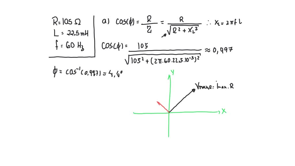
Solved A Sketch The Phasor Diagram For An Ac Circuit With A 105 Omega Resistor In Series With A 22 5 Mh Inductor The Frequency Of The Generator Is 60 0 Mathrm Hz B If The Rms
The value of resistance R shall be such that it will limit the fault current to the full rating of the largest generator or transformer. (a) Circuit Diagram (b) Phasor Diagram. Fig. 1: Resistance Grounding \[R=\frac{V_{L}}{\sqrt{3}I}\] where, R = Resistance. V L = Line volume, I = Full-load current of largest machine

Hello Friends I Hope All Of You Are Fine In Today S Tutorial We Are Gonna Have A Look At The Phasor Diagrams Of A Synchronous Gen Diagram Generator Analysis

Phasor Diagram Of Synchronous Generator Phasor Diagram Of Alternator Diagram Alternator How Are You Feeling










Comments
Post a Comment