41 call flow diagram
In the diagram below, Bob will receive a "toast" notification of an incoming call from Alice. If Bob and Alice are in a situation where they have direct connectivity to one another (i.e. located in the same office within the same building), media will actually be allowed to flow directly to one another. Download scientific diagram | Incoming call flow chart from publication: Modeling and Simulation of Patient Admission Services in a Multi-Specialty ...
Call flows plan exactly what customers will experience when they make first contact, and also show what will happen if lines are busy, unanswered, or misdirected. Below is a very basic example of what call flow diagrams look like: Depending on the industry, and the size or nature of your organization's contact center, call flows can be extremely advanced and can be designed to handle complex call scenarios. Why a successful call flow is important for your contact center
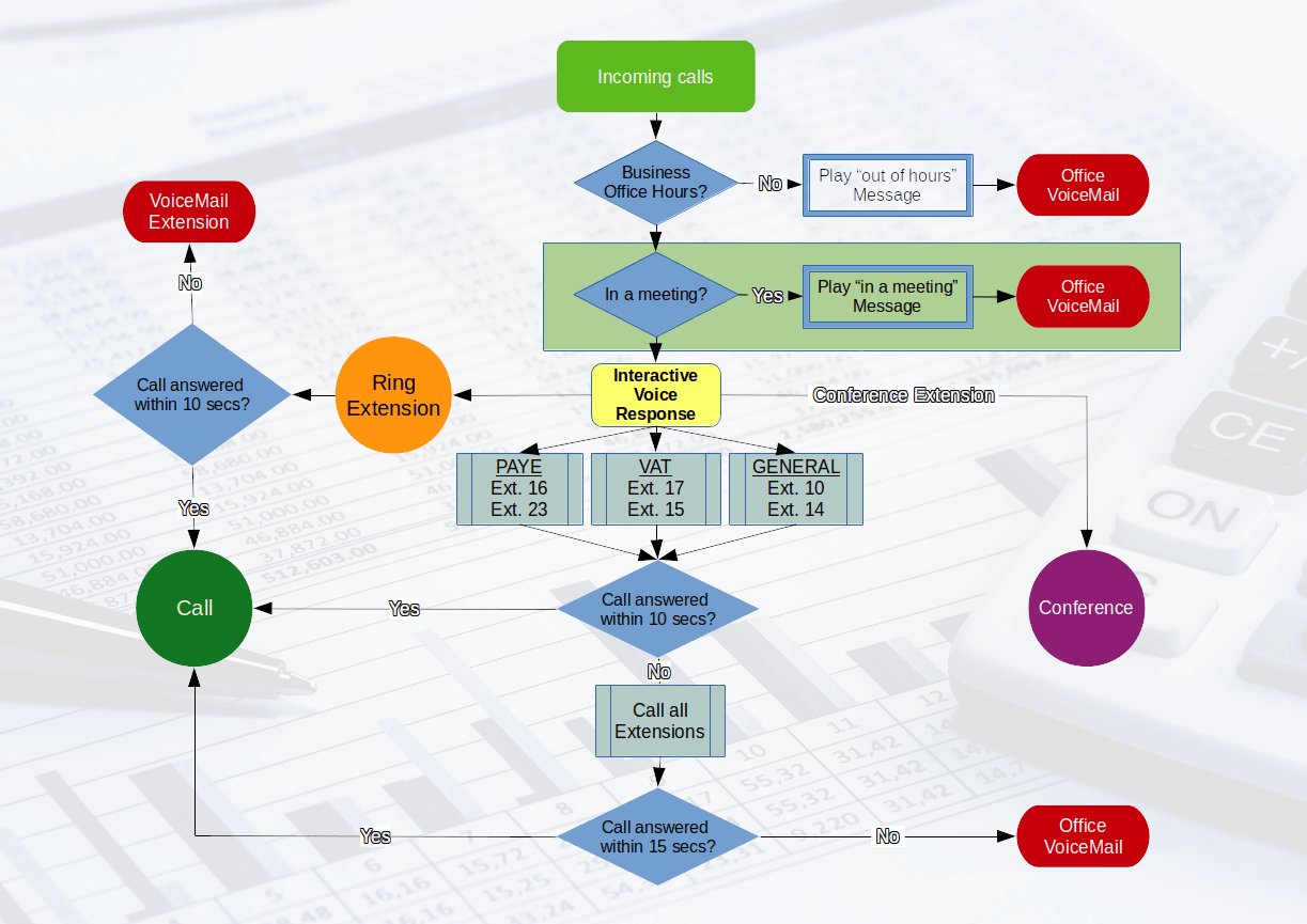
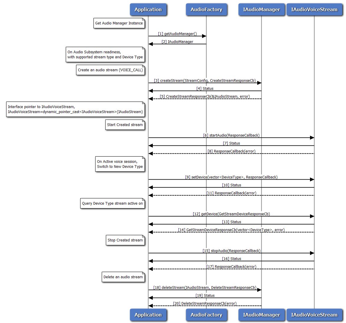
Call flow diagram
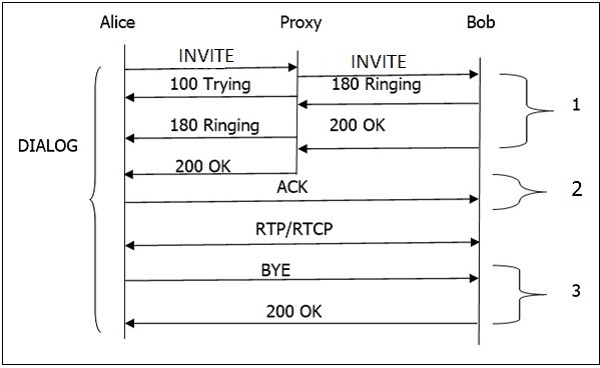
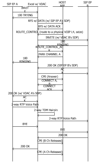
The callflow sequence diagram generator is a collection of awk and shell scripts that will take a packet capture file that can be read by wireshark and produce a time sequence diagram. This is useful to view & debug SIP callflows or other network traffic Project Samples Project Activity 5 years ago Richard Bos posted a comment on ticket #11 GSM Call Flow (GSM Originating Call) Cell Mobile Network Fixed Network Mobile Station Base Stations NSS PSTN User Mobile BSS MSC VLR PSTN EventStudio System Designer 4.0 13-Sep-08 21:38 (Page 4) ISUP RELEASED SS7 The MSC informs the PSTN that the call release has been completed. ISUP RELEASE COMPLETE SS7 The PSTN informs that call release has The following image shows the basic call flow of a SIP session. Given below is a step-by-step explanation of the above call flow − An INVITE request that is sent to a proxy server is responsible for initiating a session. The proxy server sendsa 100 Trying response immediately to the caller (Alice) to stop the re-transmissions of the INVITE request.
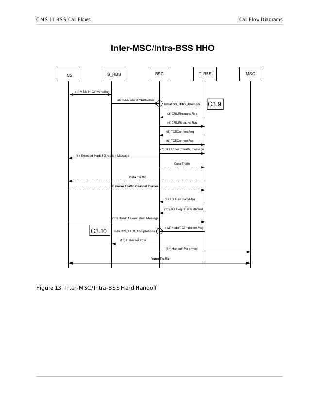
Call flow diagram. Call Flow Diagram - Screen Detailed Analysis for VoIP Welcome to the master class of Sigma Telecom and today we are going to take a picture of a call and try to tell you about the flow of a VoIP call from beginning to end. Flows are like roentgen of the VoIP calls that show the time of the call invitation, end, etc. A 3G UMTS originating voice call setup involves complex signaling to set up and release the call. RRC (Radio Resource Control) signaling between the UE and RAN sets up the radio link. RANAP (Radio Access Network Application Part) signaling sets up the session between the RAN and the Core Network (MSC). Click on the image to see the full call flow. Simple IVR Call Flow. Use Creately's easy online diagram editor to edit this diagram, collaborate with others and export results to multiple image formats. You can edit this template and create your own diagram. Creately diagrams can be exported and added to Word, PPT (powerpoint), Excel, Visio or any other document. To create a call flow diagram: Procedure In the Project Explorer view, right-click the UML package; then click Add Diagram> Call Flow Diagram. In the Call Flow Name field, type a name for the diagram, and click OK. This name is also used to name the UML collaboration and the interaction instance. The
Flowchart Symbols and Meaning - Provides a visual representation of basic flowchart symbols and their proposed use in professional workflow diagram, standard process flow diagram and communicating the structure of a well-developed web site, as well as their correlation in developing on-line instructional projects. Call Center Flow Chart [classic] by Cheyenne Arrowsling. Edit this Template. Use Creately’s easy online diagram editor to edit this diagram, collaborate with others and export results to multiple image formats. You can edit this template and create your own diagram. Creately diagrams can be exported and added to Word, PPT (powerpoint), Excel ... International Journal of Engineering Technology Science and Research IJETSR www.ijetsr.com ISSN 2394 - 3386 Volume 2 Issue 4 April 2015 Basic Introduction to GSM Architecture and Call Flow Ankita Jain,Arjun Rajput, Shubhra Dixit Amity Institute of Telecom Engineering and Management Amity University, Noida, UP Abstract-GSM Architecture is the architecture on which our telecommunication system ... The following diagram shows call flow when media bypass is enabled, the client is external, and the client cannot reach the public IP address of the Session Border Controller (media is relayed by Teams Transport Relay). The arrows and numeric values of the paths are in accordance with Microsoft Teams call flows.
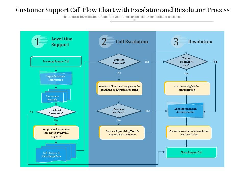
ConceptDraw DIAGRAM flowchart software will help to quickly create new flowcharts, workflow, NS Diagram, BPMN Diagram, Cross-functional flowcharts, data flow diagrams and highlight flowcharts. Feature-rich flowchart maker, free thousand flowchart examples and templates and colored symbols that will allow you to create professional looking ... Call Flow Examples (using Wireshark) In the call flow examples that follow, Wireshark was used to analyze the PCAP data. To do this in Wireshark simply open the PCAP file and navigate to Telephony > VoIP Calls. Select the call that is of interest and press the Flow sequence button. This will then display the SIP call flow diagram for that call. Call center process workflows, or flow charts, are documents that visualize the different activities done by a call center, whether it's in-house or a third-party company. Whether it's customer issue resolutions, technical support, new account creation, or other processes, the kind of high volume work call centers handle benefits from a standardized process flow. Example Call Flow 4 Call Router Call Router Overview The Call Router application lets callers speak to a specific person by saying that person's name. Using a grammar made up of the list of names plus alternate names and pronunciations, the Call Router assembles a list of all possible combinations a caller might be expected to say.
Call flow is how signaling and sessions are established across an LTE network . We will have a look at the call flow diagrams about different procedures in LTE which includes basic registration, Carrier Aggregation (band addition and removal), 4x4 MIMO activation, SMS etc. LTE Registration Tracking Area Update
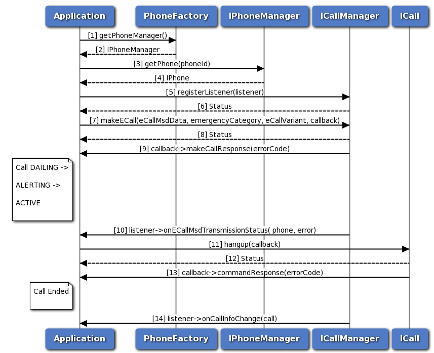
To create a call flow diagram: Procedure In the Project Explorer view, right-click the UML package; then click Add Diagram > Call Flow Diagram. In the Call Flow Name field, type a name for the diagram, and click OK. This name is also used to name the UML collaboration and the interaction instance.
This article describes how Teams uses Microsoft 365 or Office 365 call flows in various topologies. In addition, it describes unique Teams flows that are used for peer-to-peer media communication. The document describes these flows, their purpose, and their origin and termination on the network. For purposes of this article, assume the following: 1. Flow X is used by the on-premises client to communicate with the Microsoft 365 or Office 365 service in the cloud. It originates from the customer network, and it terminates as an endpoint in Microsoft 365 or Office 365. 2. Flow Y is used by the on-premises client to communicate with a service on the Internet that Microsoft 365 or Office 365 has a dependency on. It originates from the customer network, and it terminates as an endpoint on the Internet. This article covers the following information: 1. Background. Provides background information such as networks that the flows may traverse, types of traffic, connectivity guidance from the...
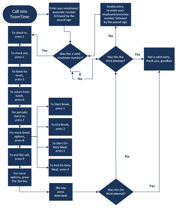
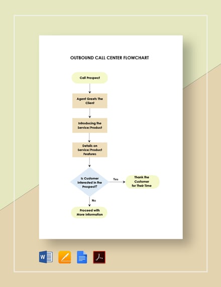
A call flow diagram is a graphical representation that provides a general structure of how to handle a call. It works similarly to a script but it doesn't provide the exact words the caller should say. What it does is guide you on how to answer a call, which path should you direct the customer next and so on.
Flowcharts are diagrams that show the steps in a process. Basic flowcharts are easy to create and, because the shapes are simple and visual, they are easy to understand. Note: You can also automatically create a basic flow chart from data by using a Data Visualizer diagram in Visio.
Thanks in advance. @bucfan609-. Attached is a rather advanced call flow diagram I created in Visio. If this does not work or you need something else, please feel free to reach out! Call_Center_-_Advanced_Call_Flow.vsd (82.5 KB) View this "Best Answer" in the replies below ». Popular Topics in VoIP.
(1) Mastering the Flow: In addition to walking the agent through the call flow, give them plenty of time to role-play with a colleague or a professional role-playing organization. Run the agent (and the call flow) through a wide variety of scenarios until they have mastered the call flow and demonstrated their ability to 'go with the flow of the conversation.
Call Flow Diagram. Here are a number of highest rated Call Flow Diagram pictures upon internet. We identified it from trustworthy source. Its submitted by presidency in the best field. We receive this nice of Call Flow Diagram graphic could possibly be the most trending topic behind we portion it in google pro or facebook.
Flowchart Tutorial (with Symbols, Guide and Examples) A flowchart is simply a graphical representation of steps. It shows steps in sequential order and is widely used in presenting the flow of algorithms, workflow or processes. Typically, a flowchart shows the steps as boxes of various kinds, and their order by connecting them with arrows.
GSM Mobile Terminated Call Flow. In this call flow we will look at how a terminating call is handled in GSM. Setting up a terminating call is a two step process. (1) Interrogation procedure to locate the subscriber (2) Actual call setup after the subscriber has been located.
ConceptDraw is Professional business process mapping software for making process flow diagram, workflow diagram, general flowcharts and technical illustrations for business documents. It is includes rich examples, templates, process flowchart symbols. ConceptDraw flowchart maker allows you to easier create a process flowchart. Use a variety of drawing tools, smart connectors, flowchart symbols ...
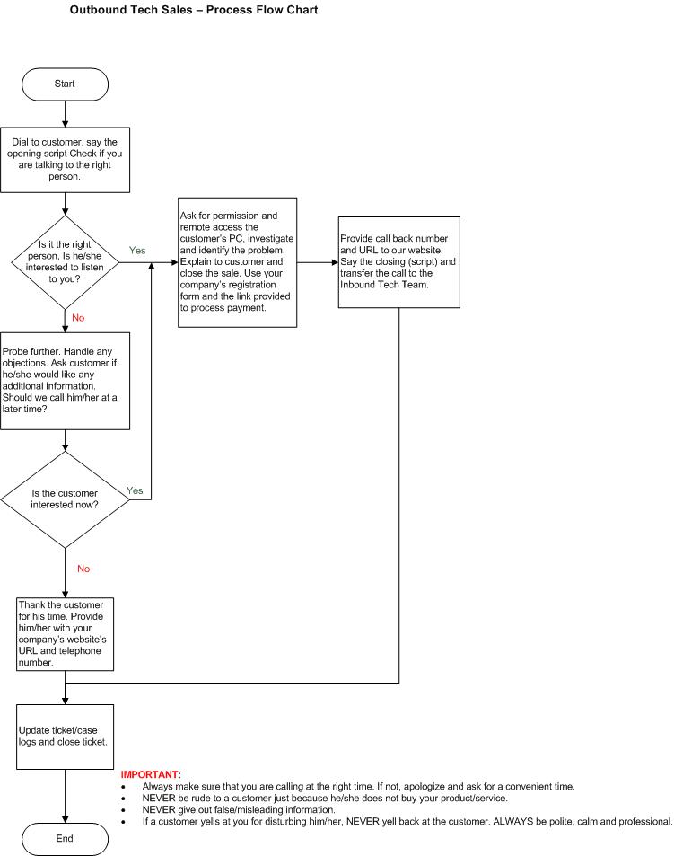
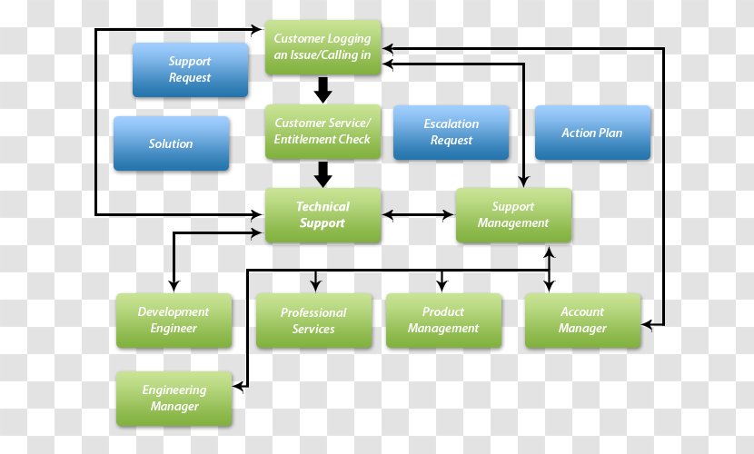
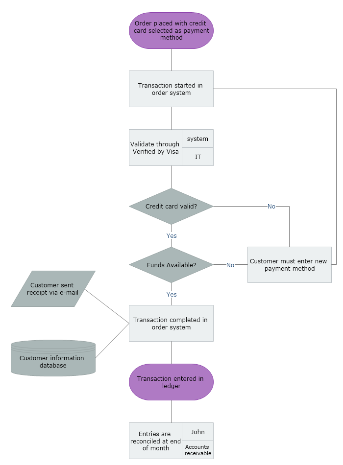
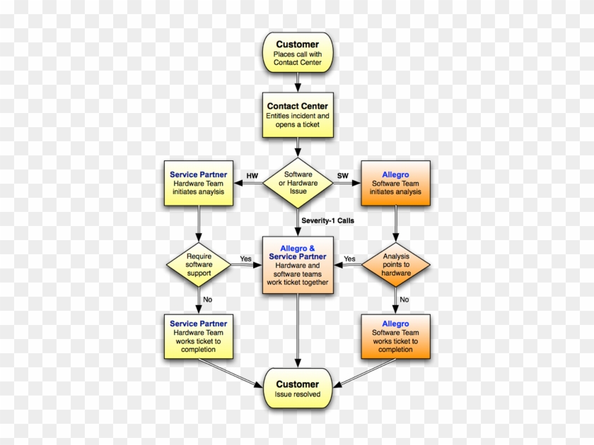
A call center process flow chart is a diagram or a graphical representation of any customer service process. In this diagram, a flowchart symbol or an icon represents each different step in a specific process. A flowchart symbol may also contain a text box that describes the step.
Figure B-2 illustrates a successful phone-call setup and call hold. In this scenario, the two end users are User A and User B. User A is located at PBX A. PBX A is connected to Gateway 1 (SIP gateway) via a T1/E1. User B is located at a Cisco SIP IP phone. Ga teway 1 is connected to th e Cisco SIP IP phone over an IP network. The call flow is as follows: 1. User A calls User B. 2.
A Call Flow is a blueprint or road map to the ultimate customer service experience for your brand. It helps your customer service agents navigate client questions and provide a sense of control from the moment the call is answered. Call flows allow you to set the tone and flow of the call to eliminate as much uncertainty as possible.
LTE Attach Procedure simple explanation with call flow diagram. prodevelopertutorial May 31, 2020. Step 1: UE will read MIB and SIB from network to synchronize with the network. Step 2: UE will send Random Access Preamble (RAP) message to eNB to achieve uplink synchronization. Step 3:
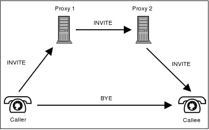
The following image shows the basic call flow of a SIP session. Given below is a step-by-step explanation of the above call flow − An INVITE request that is sent to a proxy server is responsible for initiating a session. The proxy server sendsa 100 Trying response immediately to the caller (Alice) to stop the re-transmissions of the INVITE request.
GSM Call Flow (GSM Originating Call) Cell Mobile Network Fixed Network Mobile Station Base Stations NSS PSTN User Mobile BSS MSC VLR PSTN EventStudio System Designer 4.0 13-Sep-08 21:38 (Page 4) ISUP RELEASED SS7 The MSC informs the PSTN that the call release has been completed. ISUP RELEASE COMPLETE SS7 The PSTN informs that call release has
The callflow sequence diagram generator is a collection of awk and shell scripts that will take a packet capture file that can be read by wireshark and produce a time sequence diagram. This is useful to view & debug SIP callflows or other network traffic Project Samples Project Activity 5 years ago Richard Bos posted a comment on ticket #11












![SIP call flow diagram [10] | Download Scientific Diagram](https://www.researchgate.net/profile/Iwan_Putro2/publication/43649608/figure/fig2/AS:650497572741139@1532102115639/SIP-call-flow-diagram-10.png)

Comments
Post a Comment