41 ford ignition control module wiring diagram
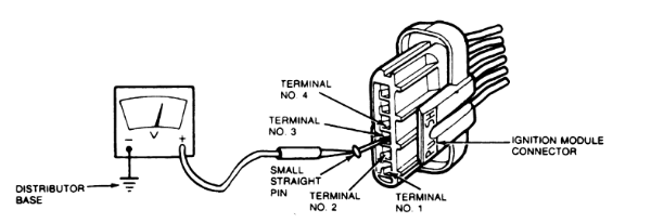
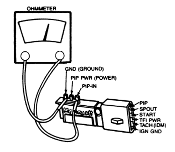
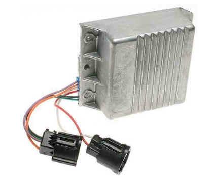
Ford Ignition Control Module Wiring Diagram - Cadician's Blog Lt1 Ignition Control Module Wiring Diagram - Wiring Library - Ford Ignition Control Module Wiring Diagram. Wiring Diagram includes several in depth illustrations that display the connection of varied items. It contains directions and diagrams for different types of wiring methods as well as other things like lights, windows, etc. Part 2 -How to Test the Ford Ignition Control Module ... Ignition System Wiring Diagram (1996 Ford E150, E250, E350) (at: troubleshootmyvehicle.com). 1992-1994 3.0L Ford Ranger: 1992-1994 3.0L Ford Ranger Ignition Control Module Wiring Diagram. TEST 1: Testing For Spark. Okay to get this show going, we need to see if the ignition system is creating and delivering spark to all 8 cylinders.
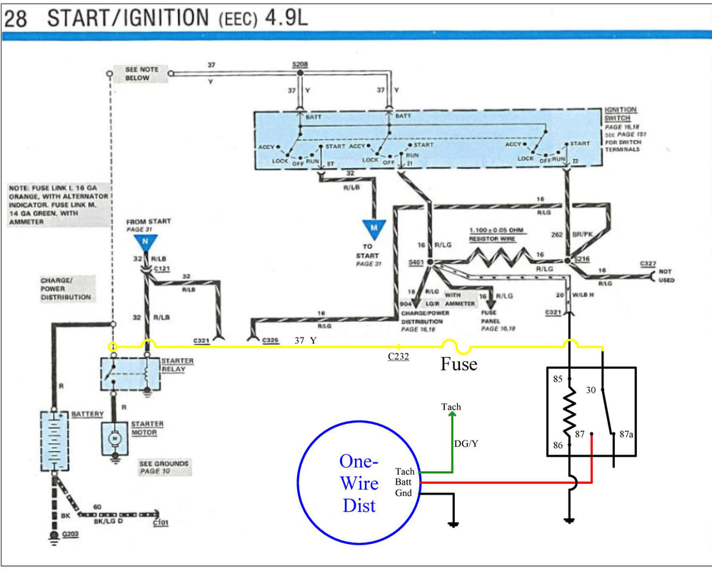
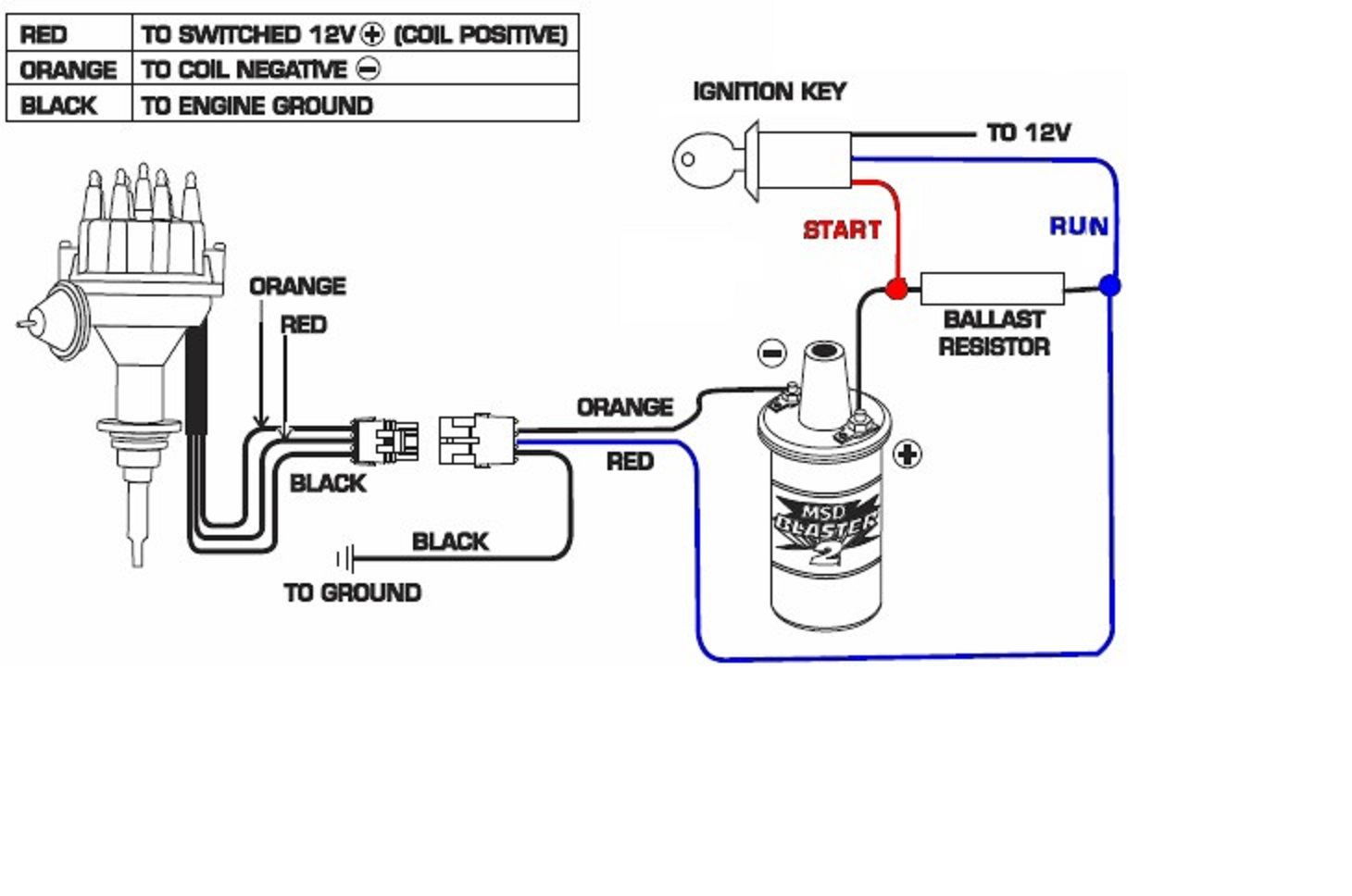
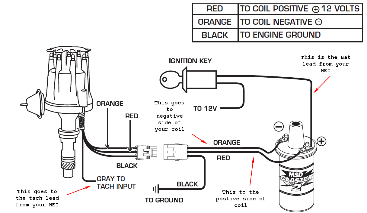
Ignition Control Module wiring diagram | SAOCA Forum All of them provide a wire to supply 12V to the coil from the ON position of the ignition switch. That is what is supplied. If you need additional wires from the coil to the HEI module and/or distributor you make them and install according to the components you are using. Here is an example of a simple diagram showing the wiring from the coil ...
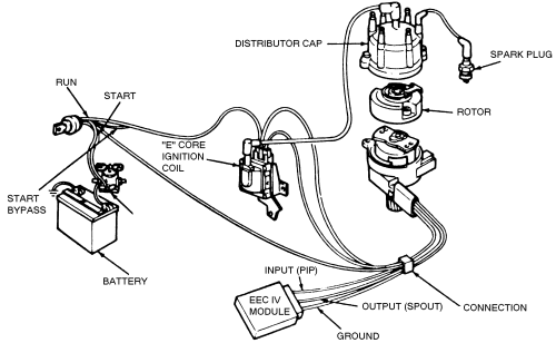
Ford ignition control module wiring diagram
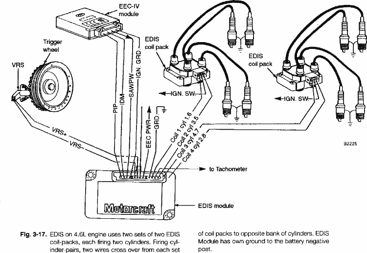
Corrected wiring diagrams for EDIS-6 ignition module ... 10 - COIL 1 (coil drive) 11 - COIL 2 (coil drive) 12 - COIL 3 (coil drive) Here's the EDIS-6 wiring diagram that I edited with the corrections: Edit: I popped open the lid on the EDIS-6 module and found that all ground pins (4, 7, and 9) are connected together on the circuit board. I can see how long ground wires between the PCM, ICM and the ... Ignition System Wiring Diagram (1994-1995 Ford F150, F250 ... The PIP (Profile Ignition Pickup) is the defacto crankshaft position sensor and is located inside the distributor (although in the wiring diagram it's not illustrated as so). NOTE: You can find the ignition control module test explained here: How To Test The Ford Ignition Control Module. You can find the 1992-1993 ignition system wiring diagram ... Ford Ignition Module F5jl 12a297 Da Wiring Diagram - mini ... Ford 8630 Wiring Diagram Free Picture Schematic. Ford 861 12 Volt Wiring Diagram. The new ICM 1U1L--12A297--DA replaces all currently available ICMs F8JL--12A297--EA F8JL--12A297--FA and F8JL--12A297--DB. Ford Fuel Gauge Wiring. 4 IB 340867 07--2007 Bill of Materials for Module Kit Ignition Replmt Ford 23L--9003676 Ref.
Ford ignition control module wiring diagram. Ford Ignition Control Module Wiring Diagram - Wiring Diagram Lt1 Ignition Control Module Wiring Diagram - Wiring Library - Ford Ignition Control Module Wiring Diagram. Furthermore, Wiring Diagram gives you time body during which the tasks are to be accomplished. You may be capable to know precisely if the tasks needs to be accomplished, that makes it much simpler to suit your needs to effectively ... Ignition Wiring Diagram Ford Expedition How To Test The Ford 4.6L, 5.4L Coil-On-Plug Ignition Coilsdfi-ferien-fussballcamps.deblisterportal.devillakarolina.deFord F-150/F-250: How to Install Rearview Backup Camera Curt Spectrum Trailer Brake Controller - 1 to 4 Axles Technical Diagrams Archives - Early Ford Bronco and Truck studio-tam.deBudgetCamper Wiring Diagram - 32000w ... Ford Ignition Wiring Diagram - CASSANDRALANDER 1986 Ford F 250 Wiring Diagram Wiring Diagram Dash . 89 Ford Ignition Module Wiring Diagram Wiring Diagram . ... Audio Control Epicenter Wiring Diagram Audio Systems Subwoofer Wi… Blog Posts. 2020 (765) Februari (145) Maret (156) April (153) Mei (153) Ford Trailer Plug Wiring Diagram ... A ignition control module wiring diagram for 1983 mustang ... 6982 Answers. SOURCE: ignition switch diagram 65 mustang. If its not on the steering column, you can figure it out using an ohmeter on the switch leads. Actually, you could figure out the one on the column that way too! just think about what the switch does in each position and attach wires that do it to the post that does it!
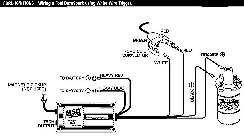
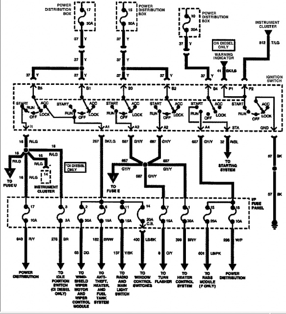
Ignition Switch Wiring Diagram - Ford Mustang Forum I can't find a wiring diagram that encompasses the ignition switch (2007 GT) and where all the wires coming out of it go to, etc. I found a "part" of it in the instrument cluster diagram but that only covers the one wire in the ignition switch plug that effects the cluster (low voltage switched power). There are other 12v switched ... Ford Ignition Control Module Wiring Diagram Database ... Ford Ignition Control Module Wiring Diagram from cloningdiagrams.altj.fr. Print the wiring diagram off plus use highlighters to trace the signal. When you make use of your finger or perhaps the actual circuit with your eyes, it is easy to mistrace the circuit. 1 trick that We 2 to printing a similar wiring plan off twice. Basic Ignition System Wiring Diagram - Wiring Diagram The purpose of the ignition system is to create a spark that will ignite the fuel air mixture in the cylinder of an engine. Basic ignition system wiring diagram. Wiring diagram for ignition coil more information find this pin and more on 63 f100 wiring by ben platt. This applies to all old cub cadet ford jacobsen john deere wheel horse case and ... Ford Duraspark Ignition Wiring Diagram - schematron.org Duraspark 2 wiring diagram along with jeep cj7 wiring diagram fuse moreover ford f vacuum diagram html moreover mustang no wires on my coil so which ones do i need moreover duraspark2 conversion furthermore ferrari engine diagram along with ford ignition control module wiring diagram in addition lights.Ford Dura-Spark II, Wiring, How ToFord ...
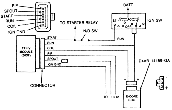
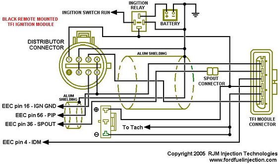
PDF Ford TFI Electronic Ignition - 49ccScoot.Com by the PCM to control engine timing via the SPOUT signal. Ford TFI gray remote-mount module wiring diagram: Note: The TFI module will fire the coil on the rising edge of either the SPOUT or PIP signal depending on the voltage at the START pin. 12V applied to the START pin will cause the TFI module to ignore the SPOUT signal and fire on the Duraspark II -- The Ford V-8 Engine Workshop Duraspark II electronic ignition was used on 1977 to 1984 Ford V-8 passenger car and light truck engines. This article refers to the Duraspark II control module with a BLUE strain relief bushing, one 4-pin connector, and one 2-pin connector. ... Note that the colors of the wires shown in the diagram below are at the module itself. The wires in ... Ford Diagrams - Wiring Wizard Here we have Ford Wiring Diagrams and related pages. Electronic Fuel Injection. Ford EFI injector wiring conversion (Bank firing to Independently fired) ... 1975-1979 DuraSpark mustang ignition control module schematic - Drawing A . Power Seats: 57-64 Mercury (57-59 seat O matic), 57-60 Edsel, 57-64 Thunderbird (4-way & 6-way ... Ignition System Wiring Diagram - Wiring Sample Dyna 2000 Ignition Wiring Diagram Dyna 2000I Ignition in Dyna 2000 Ignition Wiring Diagram image size 949 X 806 px and to view image details please click the image. This refers to the Duraspark II control module with a BLUE strain relief bushing The high voltage ignition coil wider spaced terminals of the distributor cap and. Ignition Control ...
Ford Ignition Control Module Wiring Diagram - autocardesign Ford Ignition Control Module Wiring Diagram - wiring diagram is a simplified tolerable pictorial representation of an electrical circuit. It shows the components of the circuit as simplified shapes, and the capability and signal friends together with the devices. A wiring diagram usually gives counsel more or less the relative perspective and ...
Ford Ignition Control Module Wiring Diagram - Wirings Diagram According to earlier, the traces in a Ford Ignition Control Module Wiring Diagram represents wires. Sometimes, the wires will cross. However, it does not mean link between the cables. Injunction of two wires is usually indicated by black dot on the intersection of 2 lines. There will be main lines that are represented by L1, L2, L3, and so on.
PDF Focus Wiring Diagrams - Ford Focus Systems Overview FOR1-0726c100-00-01p001-UK 100-00-01 100-00-01 11/2002 2002 Focus-1 Fuel Charging and Controls - ZETEC-E, with LPG fuel system
Ignition Module wiring diagram colors? - Ford Truck ... In order to fix electrical gremlins, I need a wiring + colors schematic of the Ignition Module in my 2002 Excursion Limited 7.3L. You can see what I'm dealing with here. I will be replacing the connectors (especially the twisted together and black taped gray line), but want to be sure what is connected to what. Any help would be appreciated!
Ignition Switch Wiring Diagram Ford - Wiring Sample Ford ignition control module wiring diagram ford 302 ignition control module wiring diagram ford ignition control module wiring diagram every electric arrangement consists of various different pieces. It shows the parts of the circuit as streamlined forms and the power as well as signal connections between the gadgets. Van ford econoline 1993 ...
Ford Duraspark Ignition Module Wiring - schematron.org This refers to the Duraspark II control module with a BLUE strain relief bushing The high voltage ignition coil, wider spaced terminals of the distributor cap, and.Sep 20, · Using and wiring the cut wiring harness (two electrical wires) that connect to the two wires coming out of the ignition module. Run a positive feed wire from ignition ...
Ford Ignition System Diagram - Wiring Diagram and ... Ford Ignition System Diagram. Ford ignition system circuit diagram part 1 duraspark ii the v 8 engine wiring 1994 eec iv tfi electronic 4 diagrams ranger lincoln control coil. Part 1 Ford Ignition System Circuit Diagram 1992 1993 F150 F250 F350. Part 1 Ignition System Circuit Diagram 1994 1995 Ford F150 F250 F350.
Ford Ignition Module Wiring Diagram - Studying Diagrams Ford Ignition Control Module Wiring Diagram wiring diagram is a simplified tolerable pictorial representation of an electrical circuit. Fords Electronic Distributorless Ignition System EDIS is an ignition system that does NOT require a cam position signalIt can function with just a variable reluctor crank position sensor and a 36-1 tooth wheel ...
2013 Ford Fusion Wiring Diagram Images - Wiring Diagram Sample 2013 Ford Fusion Wiring Diagram. 2013 Ford Fusion Wiring Diagram from . To properly read a electrical wiring diagram, one offers to know how typically the components in the program operate. For example , in case a module is usually powered up also it sends out a new signal of 50 percent the voltage and the technician will not ...
Ford Ignition Module F5jl 12a297 Da Wiring Diagram - mini ... Ford 8630 Wiring Diagram Free Picture Schematic. Ford 861 12 Volt Wiring Diagram. The new ICM 1U1L--12A297--DA replaces all currently available ICMs F8JL--12A297--EA F8JL--12A297--FA and F8JL--12A297--DB. Ford Fuel Gauge Wiring. 4 IB 340867 07--2007 Bill of Materials for Module Kit Ignition Replmt Ford 23L--9003676 Ref.
Ignition System Wiring Diagram (1994-1995 Ford F150, F250 ... The PIP (Profile Ignition Pickup) is the defacto crankshaft position sensor and is located inside the distributor (although in the wiring diagram it's not illustrated as so). NOTE: You can find the ignition control module test explained here: How To Test The Ford Ignition Control Module. You can find the 1992-1993 ignition system wiring diagram ...
Corrected wiring diagrams for EDIS-6 ignition module ... 10 - COIL 1 (coil drive) 11 - COIL 2 (coil drive) 12 - COIL 3 (coil drive) Here's the EDIS-6 wiring diagram that I edited with the corrections: Edit: I popped open the lid on the EDIS-6 module and found that all ground pins (4, 7, and 9) are connected together on the circuit board. I can see how long ground wires between the PCM, ICM and the ...










Comments
Post a Comment