42 break away systems wiring diagram
Electric Brake Controller Wiring Diagram : Elecbrakes Electric Brake Controller Wiring Diagram. Wiring Diagram. Auxiliary connection is optional, it may be connected to any 12v to 24v constant power source or left unconnected. Break away systems may be added to the service brake circuit. Elecbrakes is designed to operate 1 to 2 braked axles. Get. Wiring Diagram for Breakaway Kit. - Couplemate Trailer Parts System for Trailers. Over 2000Kg. COUPLEMATEQQ. TRAILER PARTS=$ 4WD, TRAILER, CAMPER AND CARAVAN PARTS. The Couplemate™ Break Away System is designed to ...2 pages
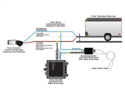
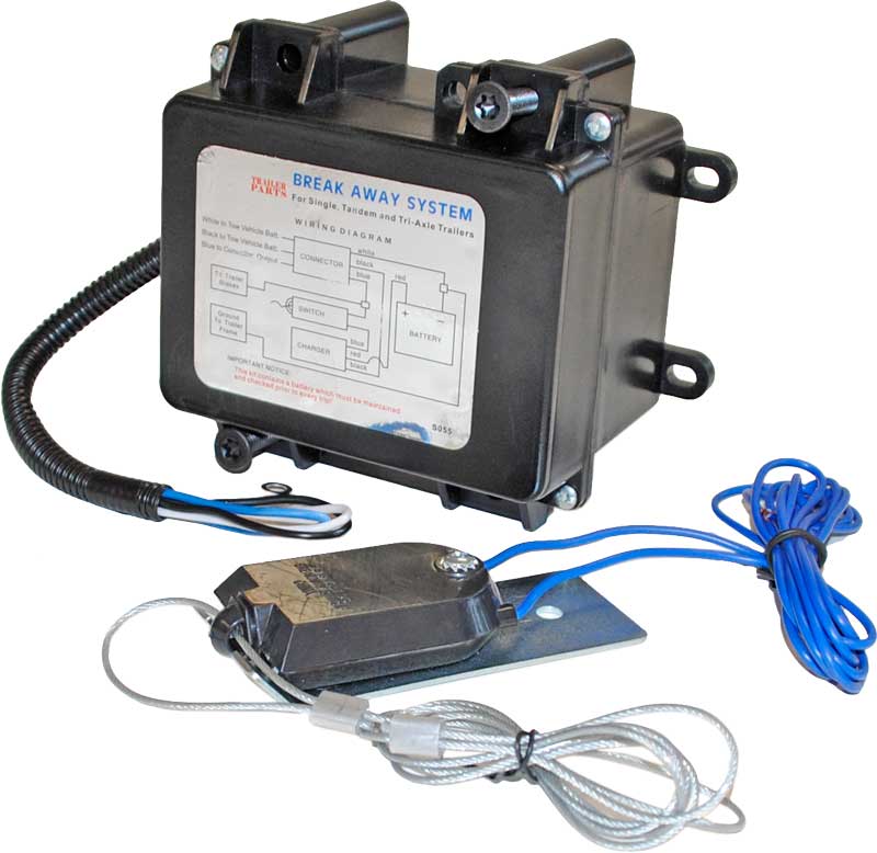
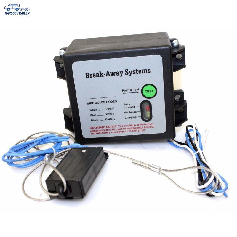
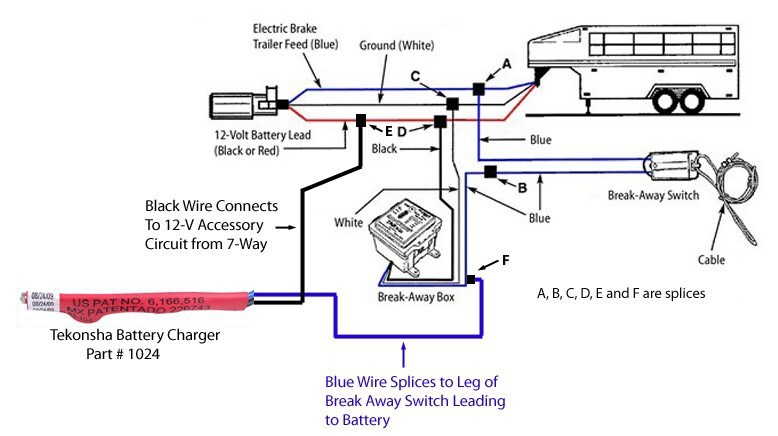
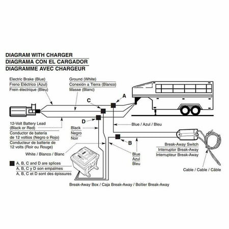
How to Wire a Trailer Break Away System and Connect ... We have a online diagram that will help you understand how the break away system is wired into your trailer. It is actually a simple installation. The system splices into the existing trailer wiring. The break away box will have 3 wires coming out of it, a black, a white, and a blue wire. The Black wire would tap into the 12 Volt accessory lead from the trailer connector, the white wire would tap into the white ground wire from the trailer connector, and the blue wire from the break away box ...
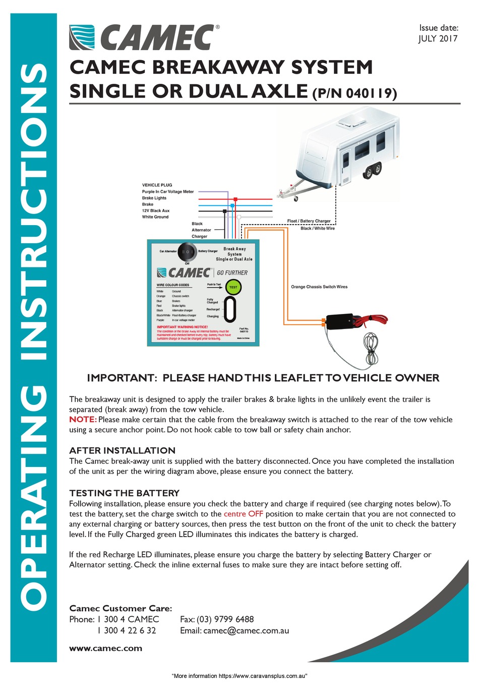
Break away systems wiring diagram
Breakaway Battery Charger Installation Instructions - Jammy ... Wire per schematic diagram. Properly insulate ... Check your breakaway system periodically to insure that wiring and connections are secure.1 page Mounting and Wiring Instructions for Brake-away Systems I. Locate secure surface on trailer to mount Break-Away Kit. 2. Route screws through provided holes in the Break-Away Kit plastic casing. Use wrench and drill to secure to trailer. 3. Next, mount Break-Away Switch close enough on trailer that cable can be attached to vehicle. 4. Follow "Wiring Instructions". WIRING INSTRUCTIONS: BREAK-AWAY SWITCH FIG. 2 The Engager Breakaway System Wiring Diagram Follow "Wiring Instructions". WIRING INSTRUCTIONS: BREAK-AWAY SWITCH FIG. 2 BREAK-AWAY SWITCH SAFETY CHAIN POCKET BUMPER CLEVIS FIG.I CABLE PIN BREAK-AWAY SWITCH FIG. 3 CABLE INSTALLATION 1. Splice one blue wire of the Break-Away Switch to the electric brake wire coming from the trailer side connector (A - see diagram on next page). 2. The Engager is designed to activate the trailer brakes in the event the trailer is separated from the towing vehicle. Trailer break-away kits are legally ...
Break away systems wiring diagram. Hopkins Breakaway System Wiring Diagram - schematron.org on Hopkins Breakaway System Wiring Diagram. These systems will require the battery be fully charged, by a trickle charger, before use. WIRING DIAGRAM ON BACK. CABLE INSTALLATION. FIG 1. FIG 2. BREAK AWAY HOPKINS BREAKAWAY SYSTEM ELECTRIC BRAKE CARAVAN TRAILER THE ENGAGER B. FREE FAST FREIGHT* GENUINE HOPKINS. wiring. Trailer Wiring and Brake Control Wiring For Towing Trailers The P3 electronic trailer brake control, for 1 to 4 Axle Trailers, is proportional. Distinct, easy to see LCD display with multiple color and contrast options. Allows you to switch between Electric and Hydraulic brakes. Prodigy trailer brake control is the latest and most intelligent brake control from Tekonsha. How Do You Wire A Trailer Break Away - U Wiring A wiring diagram is a simplified conventional pictorial depiction of an electric circuit. The breakaway switch is the brains of the operation. This short video is about trailer brakes electric brakes and wiring. Trailer Breakaway Wiring Schematic. If necessary extend the wire from the trailer breakaway switch with 14-gauge automotive. Hopkins Engager Hd Wiring Diagram - U Wiring JJThe Engager Break-Away System is designed to bring trailers safely to a stop by activating electric brakes should a trailer be. The Engager Breakaway System Wiring Diagram. The black wire on the Engager breakaway system 20099 will be connected to a 12v auxiliary power wire coming off of the trailer connector.
The Trailer Breakaway Kit And How To Use It - Mechanical ... The battery in the trailer breakaway kit doesn't do anything else. Wiring Up Your Trailer Breakaway Kit. Here is a wiring diagram for your Trailer Breakaway Kit. This is typical, but check your system to be sure the wires (colors) are the same. This little bit of schematic attaches into the full trailer wiring diagram from our other article. Bright Way Group Break Away Kit Wiring Diagram - easywiring Splice one blue wire of the break away switch to the electric brake wire coming from the trailer side connector a see diagram on next page. Note refer to the attached wiring diagram for addi tional information. Connect one of the black wires to the breakaway battery s positive terminal. Variety of trailer breakaway wiring schematic. PDF 6000 fitting instuctions page 3 - Easytow WIRING DIAGRAM BREAKSAFE BREAKSAFE Break-away switch Black. 12 volt auxiliary line. Normally Pin 2 Red. Stop light circuit Normally Pin 6 Both orange wires to break-away switch Blue to positve supply from electric brake contoller. Normally Pin 5 White. Earth return from trailer brakes. Normally Pin 3 Purple to Breaksafe Remote Monitor B l u e W h i t e Red Purple Black Orange Breakaway Kit Installation for Single and Dual Brake Axle ... 1. Splice one of the two wires coming out of the breakaway switch into the trailer brake wire running from the trailer connector to the brakes. 2. Open the battery box and connect the second wire coming out of the switch to the positive post (red) on the battery. This connection will send power to the breakaway switch.
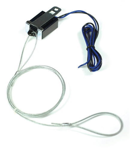
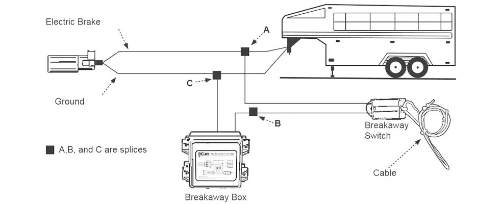
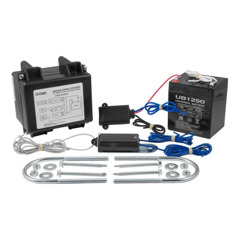
Trailer Brake Wiring Diagram With Breakaway - easywiring The trailer wiring diagram shows this wire going to all the lights and brakes. Blue wires are interchangeable on the break away switch 3. A wiring diagram is a simplified conventional pictorial depiction of an electric circuit. If not the arrangement will not function as it ought to be. Wiring Diagram for Trailer Breakaway Kit | etrailer.com I also attached an install video that shows the kit installed as well as a diagram for trailer breakaway wiring as well. The white wire is the ground wire. PDF Cable - Trailer Wiring Solutions, Brake Controllers, RV Levels 1. Splice the blue wire of the Break-Away Switch to the electric brake wire coming from the trailer side connector 2. Connect the black (labeled battery) wire of the Break-Away Switch to the blue wire (labeled brake) from the Break-Away Box 3. Splice white wire from Break-Away Box to existing ground wire on trailer or ground directly to trailer frame 4. The ENGAGER - Hopkins Towing Solutions 1. Splice one blue wire of the Break-Away Switch to the electric brake wire coming from the trailer side connector (A - see diagram on next page). 2. Connect other blue wire of Break-Away Switch to the blue wire (labeled "Brake") from the Break-Away box (B). (Note: Blue wires are interchangeable on the Break-Away Switch.) 3.
The Engager Breakaway System Wiring Diagram Follow "Wiring Instructions". WIRING INSTRUCTIONS: BREAK-AWAY SWITCH FIG. 2 BREAK-AWAY SWITCH SAFETY CHAIN POCKET BUMPER CLEVIS FIG.I CABLE PIN BREAK-AWAY SWITCH FIG. 3 CABLE INSTALLATION 1. Splice one blue wire of the Break-Away Switch to the electric brake wire coming from the trailer side connector (A - see diagram on next page). 2. The Engager is designed to activate the trailer brakes in the event the trailer is separated from the towing vehicle. Trailer break-away kits are legally ...
Mounting and Wiring Instructions for Brake-away Systems I. Locate secure surface on trailer to mount Break-Away Kit. 2. Route screws through provided holes in the Break-Away Kit plastic casing. Use wrench and drill to secure to trailer. 3. Next, mount Break-Away Switch close enough on trailer that cable can be attached to vehicle. 4. Follow "Wiring Instructions". WIRING INSTRUCTIONS: BREAK-AWAY SWITCH FIG. 2
Breakaway Battery Charger Installation Instructions - Jammy ... Wire per schematic diagram. Properly insulate ... Check your breakaway system periodically to insure that wiring and connections are secure.1 page













Comments
Post a Comment