43 Allen Bradley Safety Relay Wiring Diagram
PDF Next Generation Guardmaster Safety Relay (GSR) Wiring Diagram Next Generation Guardmaster Safety Relay (GSR) Notes for Example Wiring Diagrams Note 1 In the wiring diagrams that are shown in this publication, the type of Allen-Bradley® Guardmaster® device is shown as an example to illustrate the circuit principle. For special applications, the choice of device type is based on the suitability of allen bradley safety control relay wiring diagram ... Find your allen bradley safety control relay wiring diagram here for allen bradley safety control relay wiring diagram and you can print out. Search for allen bradley safety control relay wiring diagram here and subscribe to this site allen bradley safety control relay wiring diagram read more!
PDF Guardmaster 440C-CR30 Configurable Safety Relay User Manual Purpose of this Manual This manual is a reference guide for the CR30 safety relay, plug-in modules and accessories. It describes the procedures you use to install, wire, and troubleshoot your relay. This manual: • explains how to install and wire your relay • gives an overview of the CR30 safety relay system

Allen bradley safety relay wiring diagram
› resources › short-circuit-currentShort Circuit Current Ratings for Combination Motor ... - UL Covering the application of individual components, including a disconnecting means, an overcurrent protective device, motor controller and motor overload protection, and as a combination motor controller with specified ratings, including an SCCR. Allen Bradley Safety Relay Wiring Diagram - Wiring Diagram Allen Bradley Wiring Schematics | Manual E-Books - Allen Bradley Safety Relay Wiring Diagram Wiring Diagram includes several in depth illustrations that show the relationship of assorted products. It includes instructions and diagrams for different types of wiring techniques and other things like lights, home windows, etc. PDF Connection examples for wiring the safety relay G1501S
Allen bradley safety relay wiring diagram. Miniature "Ice Cube" Relays | Allen-Bradley United States Offers 7 or 10 A contact ratings. Includes standard ON/OFF flag indicator. Includes electrical schematic on faceplate, clear cover for visual inspection. Offers incorporated manual override lever (-3 option) with the existing push-to-test button. Includes optional lighted status indicator, push-to-test, and manual override. Essential Components. PDF MSR127 Minotaur Monitoring Safety Relays Installation ... MSR127 Minotaur Monitoring Safety Relays Installation Instructions Safety Input The safety input can be single channel or dual channel. According to the wiring inputs, cross-loop monitoring of the inputs is enabled or disabled. Crossloop monitoring can be enabled for 2-channel safety inputs in 4wire connection S11-S12, S21-S22. PDF Guardmaster Configurable Safety Relay Wiring Diagram The CR30 safety relay performs the logic that monitors the interlock and the drive, and allows access to the hazard under safe conditions. For partial body access, the 440G-LZ can be substituted for the TLS-ZR. PDF Safety - MSR127RP/TP Safety Classification Cat. 4 per EN 954-1 (ISO 13849-1), SIL CL3 per EN IEC 62061, PLe per ISO 13849-1 ... Block Diagram Typical Wiring Diagrams Light Curtain, Monitored Manual Reset, Monitored Output Single Channel E-Stop, Automatic Reset, No Output Monitoring
Allen Bradley Safety Relay Wiring Diagram - Wirings Diagram There are two things which are going to be present in any Allen Bradley Safety Relay Wiring Diagram. The first element is symbol that indicate electrical element in the circuit. A circuit is generally composed by various components. Another thing that you will come across a circuit diagram would be lines. Allen Bradley GuardMaster Safety Relay Wiring Tutorial Allen Bradley safety relays have been an industry standard for decades. A wide range of solid state as well as relay based safety circuits have been designed and sold by the company. Furthermore, safety programmable logic controllers have also been introduced to the market and are widely used in the industry. › manual › 1312887ALLEN-BRADLEY POWERFLEX40 USER MANUAL Pdf Download | ManualsLib Page 26 Aotewell Ltd Industry Automation 1-16 Installation/Wiring Figure 1.5 Control Wiring Block Diagram Typical Typical Enable Jumper (1)(4) SRC Wiring SNK Wiring Stop Start/Run FWD Direction/Run REV Digital Common Digital Input 1 Digital Input 2 Digital Input 3 Digital Input 4 Opto Common +24V +24V DC... Allen-Bradley PointIO Safety Modules Wiring and ... Diagram 1.1-Allen Bradley 1734-IB8S module Safety PointIO Hardware Overview & Wiring. The 1734-IB8S and OB8S are 8-point modules for their respective inputs or outputs. Looking at these modules we notice they have 16 channels available with similar wiring schemes. However, the difference is in the test points on the 1734-IB8S safety input module.
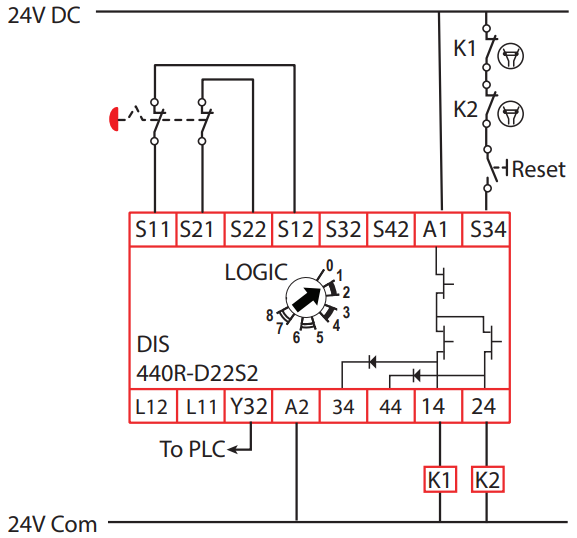
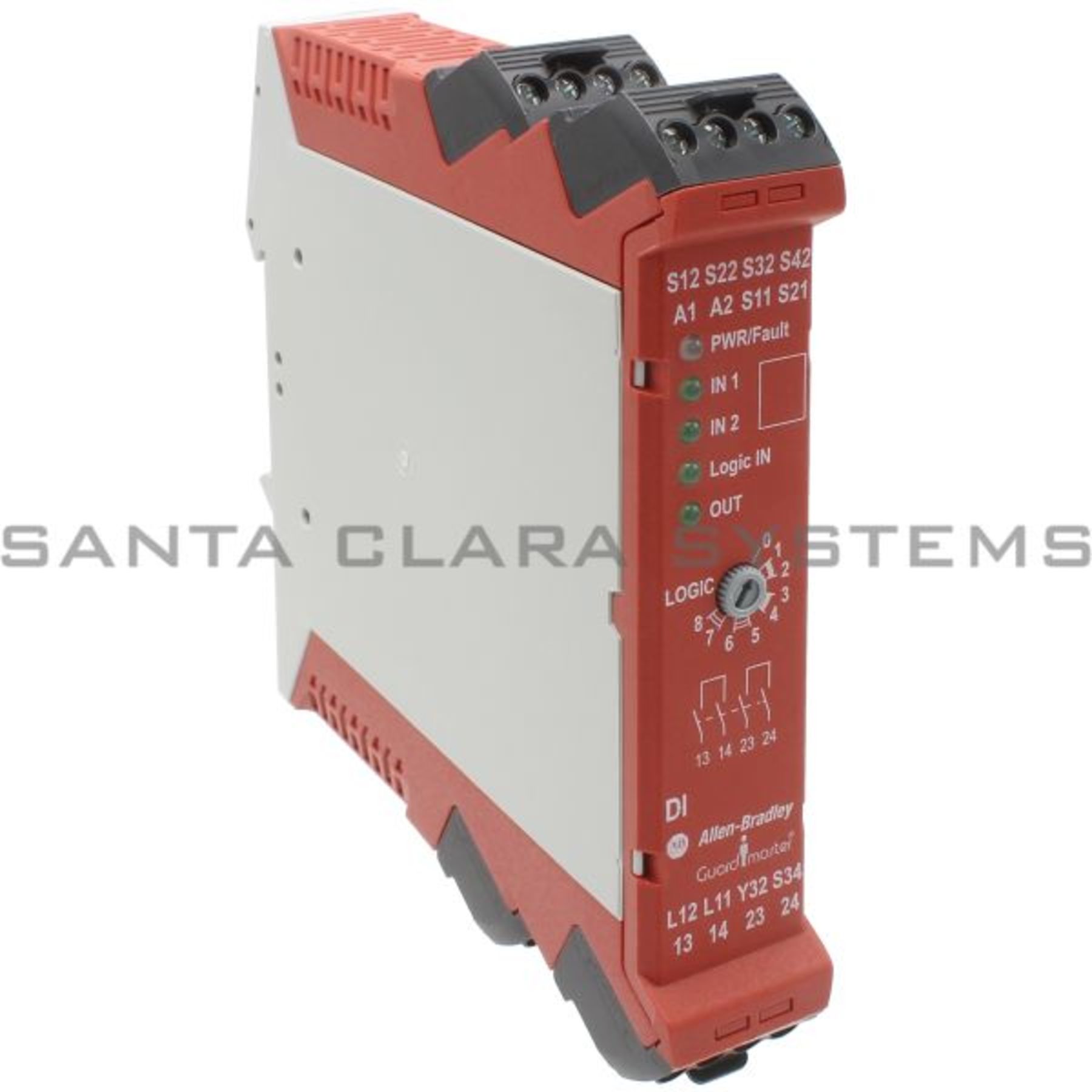
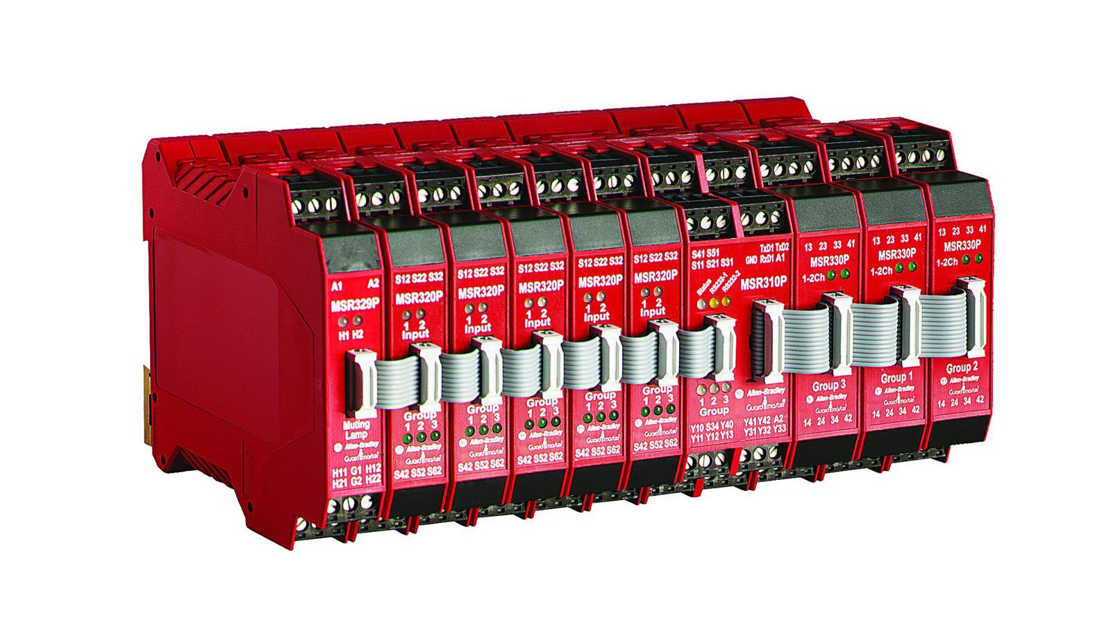
440R Guardmaster Safety Relays | Allen-Bradley Australia Allen-Bradley® Guardmaster® smart safety devices that feature ... Next Generation Guardmaster Safety Relay (GSR) Wiring Diagram SAFETY-WD001 Technical Documentation Center. Details. Technical Documentation Center Find recommended technical specifications, installation instructions and manuals, organized by product family. ... PDF Bulletin 700-P Heavy-Duty Industrial Relays Allen-Bradley distributor. Electrically Held Relays — Typical Wiring Diagrams Contacts Contact Arrangement and Markings Open Type Relay Rail Mount Open Type DIN Rail Mount N.O. N.O. Cat. No. Cat. No. 2 — 4-Pole Relay 700DC-PK200 ⊗700DC-PK200D 4— 700DC-PK400⊗ 700DC-PK400D⊗ 6 — 8-Pole Relay 700DC-PK600 ⊗700DC-PK600D PDF Bul. 440R - Guardmaster Safety Relays (DI, DIS, SI, CI ... Single-wire safety output connects to single-wire safety input relays while maintaining SIL 3, PLe Guardlocking with proximity sensors ... Block Diagrams Dual Input Relay (DI) Safety Outputs (N.O.): 13-14, 23-24 PWR IN1 IN2 LOGIC IN OUT PWR mon. A1 A2 S11 S21 S12 S22 S32 S42 IN1 IN2 L12 L11 AND/OR AND/OR Logic K1 K2 440r-d22r2 Wiring Diagram Buy Allen Bradley Guardmaster Configurable 24 V dc Safety Relay Dual Channel with 2 Safety Contacts and 1 Auxilary Contact R-S12R2. Browse our latest. R — Guardmaster® Safety .. Typical Wiring Diagram . the relay recognizes that a mat is wired to the input rather than a N.C. safety switch with a cross.Sep 28, · BMW Wiring Diagram. Truly, we ...

440R-S13R2 - Guardmaster Compatibility Input Safety Relay (CI ...
Allen Bradley Msr127tp Wiring Diagram - Diagram Allen bradley safety relay wiring diagram. Allen bradley msr127tp wiring diagram. Notes for Example Wiring Diagrams Note 1 In the wiring diagrams that are shown in this publication the type of Allen-Bradley Guardmaster device is shown as an example to illustrate the circuit principle. In the mean time lets discuss the wiring programing of the ...

Next Generation Guardmaster Safety Relay (GSR) - PDF Free ...
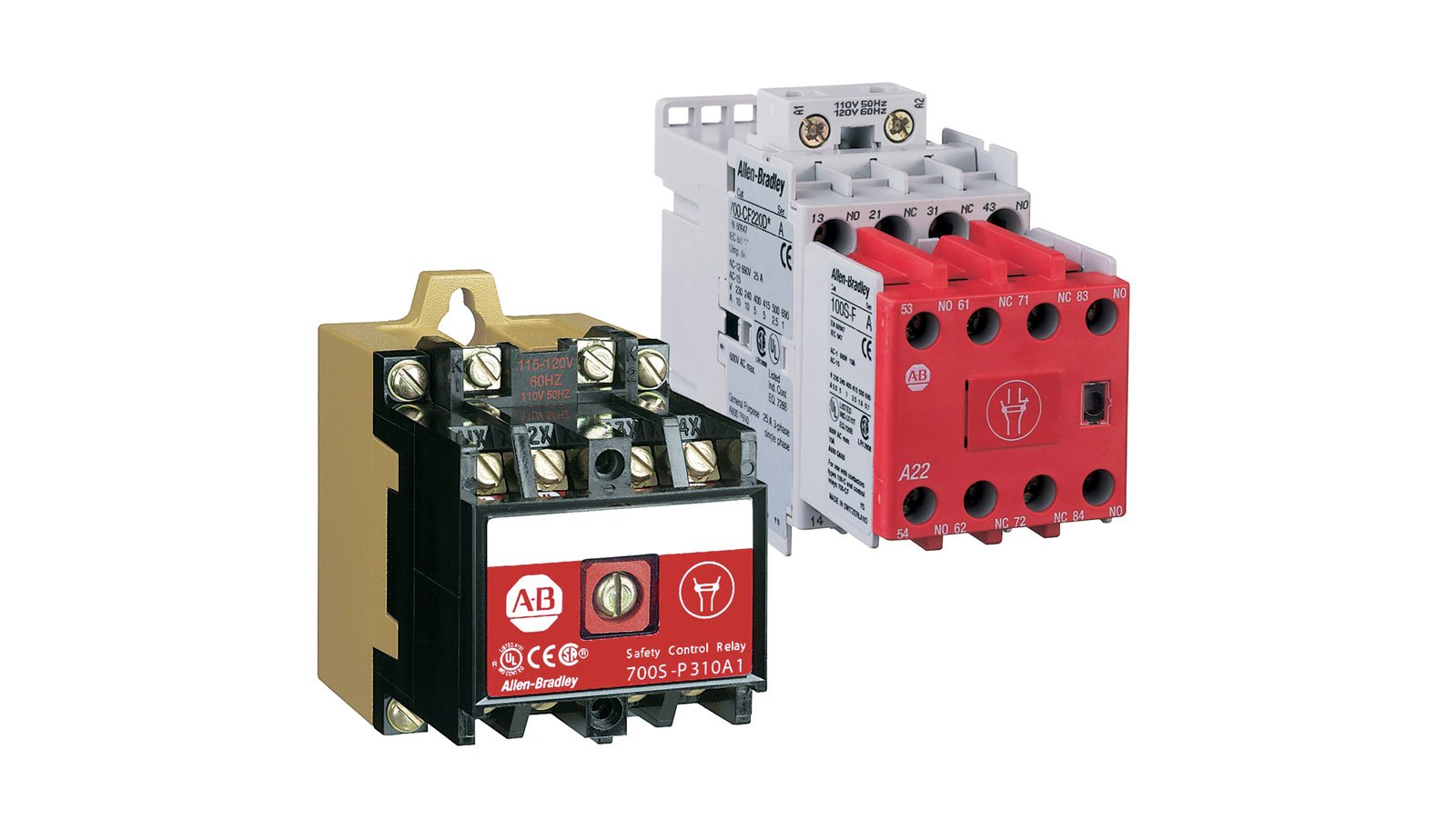
IEC Safety Contactors | Allen-Bradley United States IEC Safety Contactors. Our Bulletin 100S/104S IEC Safety Contactors provide mechanically linked, or mirror contact, performance up to 750 A, which is required in feedback circuits for modern safety applications. Our Bulletin 100S Safety Contactors use mirror contacts to provide safe isolation of hazardous motion loads.

Safety Relay Guardmaster 440R-M23141 Allen-Bradley MSR138DP ...
allen bradley guardmaster safety relay wiring diagram ... Allen Bradley Safety Relay Wiring Diagram - allen bradley guardmaster safety relay wiring diagram, allen bradley safety relay wiring diagram, Every electric structure consists of various distinct pieces. Each component ought to be placed and connected with other parts in particular way. If not, the…
Safety - MSR127RP/TP
allen bradley safety relay wiring diagram | Wirings Diagram Find your allen bradley safety relay wiring diagram here for allen bradley safety relay wiring diagram and you can print out. Search for allen bradley safety relay wiring diagram here and subscribe to this site allen bradley safety relay wiring diagram read more!
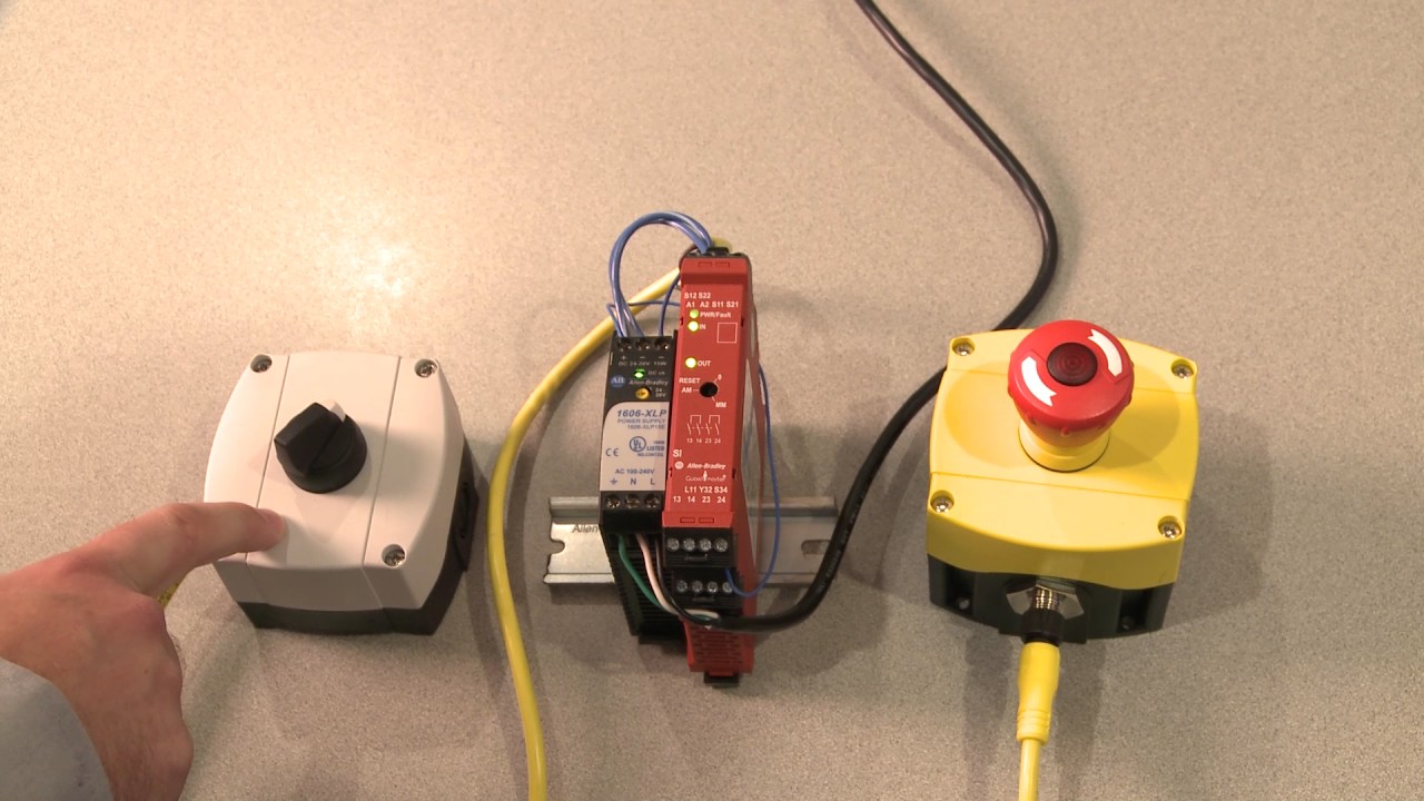
Allen Bradley GuardMaster Safety Relay Wiring Tutorial
› manual › 1252525ALLEN-BRADLEY POWERFLEX400 USER MANUAL Pdf Download | ManualsLib Page 29 Installation/Wiring 1-19 Table 1.H Relay Terminal Designations and DIP Switches No. Signal Default Description Param. #1 Relay N.O. Ready/Fault Normally open contact for No. 1 output relay. T055 #1 Relay Common – Common for output relay. #1 Relay N.C. Ready/Fault Normally closed contact for No.

440R-H23177 Allen Bradley GUARDMASTER AB SAFETY RELAY / 2 NO 1NC OUT 440R H23177
PDF 700-2.14: Safety Relays - Rockwell Automation This publication describes the operation of a safety relay, discusses applications, outlines some of the standards that reference safety, and provides specifications for Allen-Bradley safety relays. For safety relay technical and application support, call 1-888-790-8377. Additional Literature for Safety-Related Issues:
440R Guardmaster Safety Relays | Allen-Bradley United States
Safety Relays | Allen-Bradley United States Safety Relays check and monitor a safety system and either allow the machine to start or execute commands to stop the machine. Single-function safety relays are the most economical solution for smaller machines where a dedicated logic device is needed to complete the safety function. ... This relay is completely integrated with Allen-Bradley ...

Safety Function - Rockwell Automation | Manualzz
PDF Guardmaster Safety Relays User Manual The examples and diagrams in this manual are included solely for illustrative purposes. Because of the many variables and ... Allen-Bradley distributor or RockwellAutomation sales representative. ... Safety relays use single wire safety (SWS) signals that allow multiple safety
Next Generation Guardmaster Safety Relay | Manualzz
440R S12R2 Ab Guardmaster Safety Relay ... - Wiring Diagram As stated earlier, the traces in a Allen Bradley Safety Relay Wiring Diagramrepresents wires. Sometimes, the wires will cross. But, it doesn't imply connection between the wires. Injunction of 2 wires is generally indicated by black dot on the intersection of two lines. There'll be main lines which are represented by L1, L2, L3, and so on.

Allen Bradley 440r-c23018 Safety Relay Ser B En602041 ...
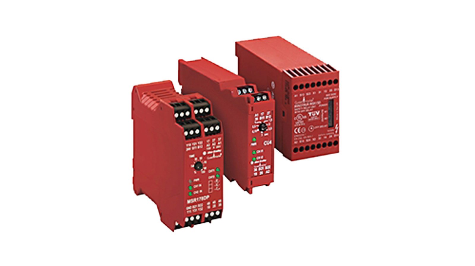
Single-function Safety Relays | Allen-Bradley United States Our MSR100 Single-function Safety Relays support a wide variety of input devices and output configurations. These relays are ideal for relatively small safety applications and single zone control and available in electromechanical version, or solid-state models for applications involving high cycle rates.

Interlock Architectures – Pt. 4: Category 3 - Control Reliable
PDF Allen-Bradley 440R-N23113 - Harvard University The Allen‐Bradley Guardmaster Minotaur MSR126R/T is a safety monitoring relay that provides the very basics for safety control systems in a 22.5 mm package. The MSR126R/T is designed for connection to a single channel safety gate, a single channel e‐stop or a light curtain that provides cross fault detection. The
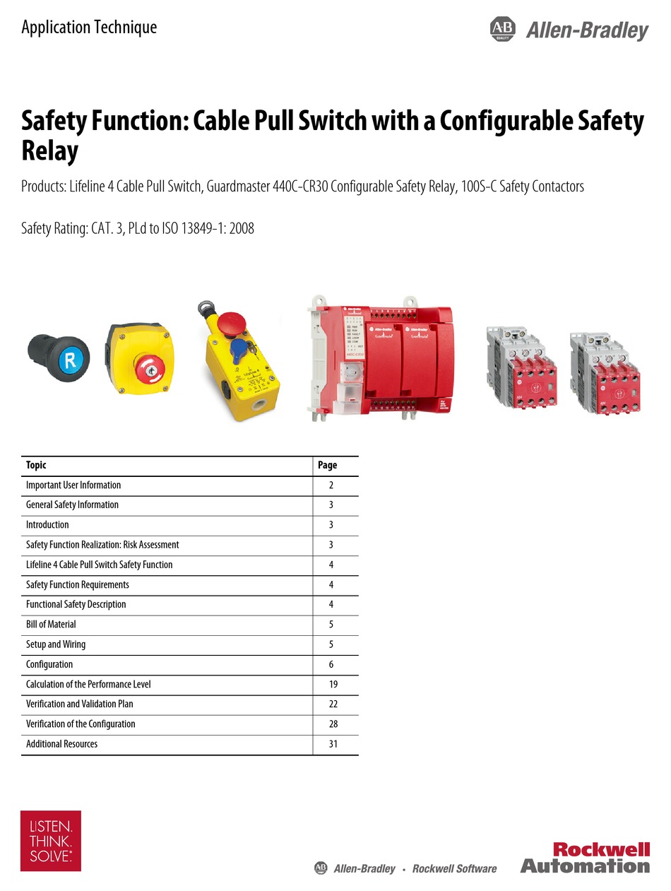
ROCKWELL AUTOMATION ALLEN-BRADLEY LIFELINE 4 APPLICATION ...
PDF Logic Single-Function Safety Relays - Harvard University The outputs include three normally open safety-rated outputs as well as one normally closed auxiliary output. The safety outputs have independent and redundant internal contacts to support the safety function. The auxiliary output is a nonsafety output intended to provide an external signal about the status of the safety outputs. Features

How to wire Safety Relay ? Emergency Stop Dual Channel Monitoring with reset || Easy Explained
› book › exportAllen Bradley's PLC Programming Handbook - PLCdev Allen Bradley offers as a free download a software package called RSLogix Micro Starter Lite which is essentially the same programming environment as RSLogix 500. On top of that, they also offer RSLogix Emulate for free so that you don’t even need a PLC to run and test your ladder logic. Keep reading and I’ll show you how to ...
Guardmaster Configurable Safety Relay Wiring Diagram
literature.rockwellautomation.com › idc › groupsBulletin 700-HPS PCB Pin Style Safety Control Relay 700 ... PCB Pin Style Safety Control Relay Features These small relays feature mechanically linked contacts required for safety circuits as per EN 50205 (Type B ) Visual • Red cover provides quick identification of safety circuits • Wiring diagram on top faceplate Contact material options • Silver nickel (AgNi) • Silver nickel with gold plating ...
Guardmaster 440C-CR30 Configurable Safety Relay User Manual
Allen Bradley GuardMaster Safety Relay Wiring Tutorial ... Allen Bradley GuardMaster Safety Relay Wiring TutorialVisit for more Tutorials, Information & to connect with the CommunitySafety C...
Guardmaster Safety Relays User Manual
literature.rockwellautomation.com › idc › groups1747-6.21, SLC 500 Fixed Hardware Style Installation and ... any particular installation, the Allen-Bradley Company cannot assume responsibility or liability for actual use based on the examples and diagrams. No patent liability is assumed by Allen-Bradley Company with respect to use of information, circuits, equipment, or software described in this manual.
Troubleshooting a Wiring Fault with Rockwell Automation Guardmaster Safety Relays
60 Lovely Allen Bradley Guardmaster Safety Relay Wiring ... 60 Lovely Allen Bradley Guardmaster Safety Relay Wiring Diagram- A manage relay is used in the automotive industry to restrict and modify the flow of electricity to various electrical parts inside the automobile. They allow a small circuit to control a later flow circuit using an electromagnet to rule the flow of electricity inside the circuit.

Emergency Stop Circuit - PLCS.net - Interactive Q & A
PDF Connection examples for wiring the safety relay G1501S
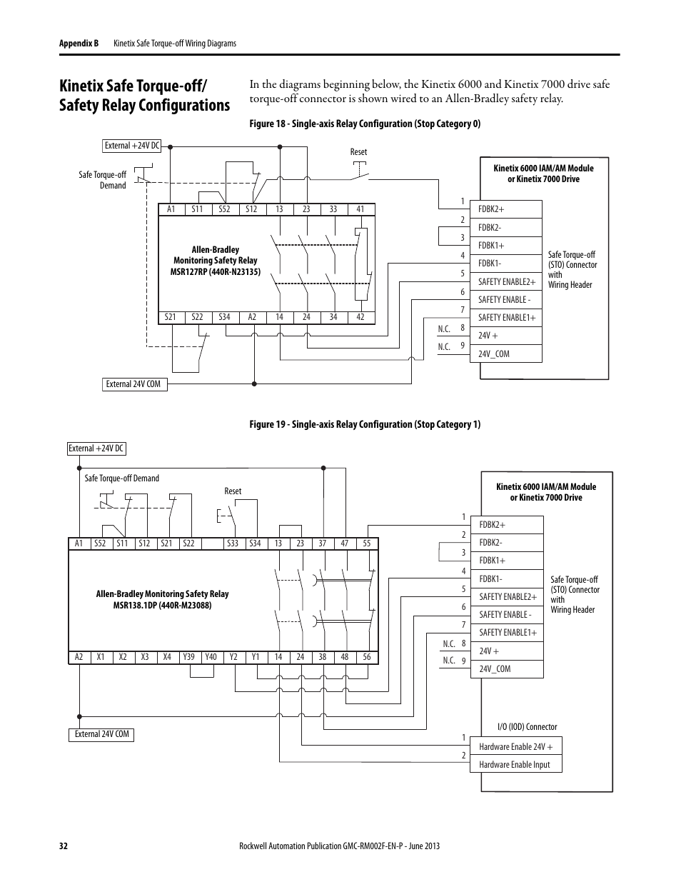
Rockwell Automation 2099-BMxx-S Kinetix Safe Torque-off ...
Allen Bradley Safety Relay Wiring Diagram - Wiring Diagram Allen Bradley Wiring Schematics | Manual E-Books - Allen Bradley Safety Relay Wiring Diagram Wiring Diagram includes several in depth illustrations that show the relationship of assorted products. It includes instructions and diagrams for different types of wiring techniques and other things like lights, home windows, etc.

Allen Bradley GuardMaster Safety Relay Wiring Tutorial
› resources › short-circuit-currentShort Circuit Current Ratings for Combination Motor ... - UL Covering the application of individual components, including a disconnecting means, an overcurrent protective device, motor controller and motor overload protection, and as a combination motor controller with specified ratings, including an SCCR.
Single-function and Specialty Relays | Allen-Bradley United ...

Safety Relay png images | PNGEgg
Safety Relays | Allen-Bradley United States
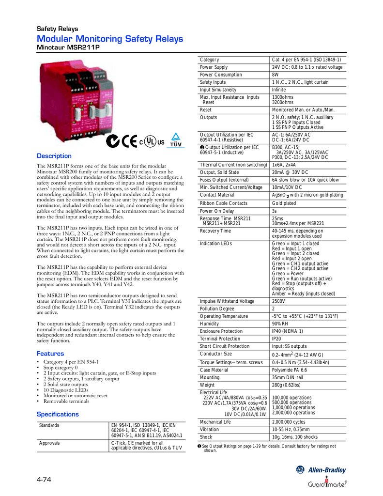
ALLEN-BRADLEY MSR211P

Allen Bradley GuardMaster 440R-ZBR520AZ1 Safety Relay ***Price Reduced*** | Daves Industrial Surplus LLC

440R-N23132 Ser. C 440RN23132Ser. C - Allen-Bradley Guard Safety Relay 440R-N23132 Ser. C (

Guide to Safety Relays and Safety Circuits
IEC Safety Control Relays | Allen-Bradley United States

Allen Bradley 440R-ZBR520AZ1 Safety Relay - Used
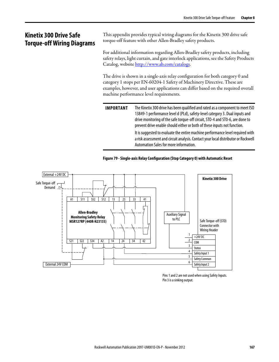
Kinetix 300 drive safe torque-off wiring diagrams | Rockwell ...

AB-S 440R-GL2S2T Guardmaster GLT Safety Relay
440R-D22R2 Allen Bradley In stock and ready to ship - Santa ...
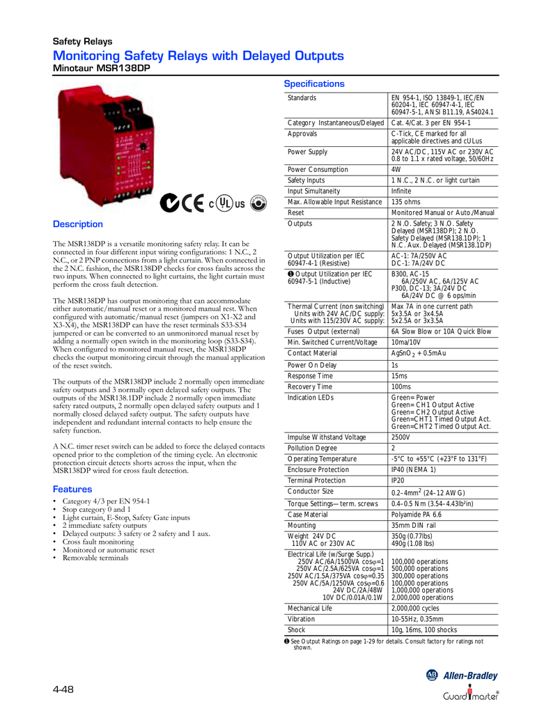
ALLEN-BRADLEY MSR138DP
Safety Relays | Allen-Bradley New Zealand

Guardmaster Configurable Safety Relay Wiring Diagram

AB Safety Relays Help. : r/PLC

Emergency Stop Circuit - PLCS.net - Interactive Q & A

Allen Bradley GuardMaster Safety Relay Wiring Tutorial
Safety Relays | Allen-Bradley United States
440R-S07282 | Allen Bradley Guardmaster Safety Relay - With 2 ...
Door Monitoring Interlock Switch with a Safety Relay and ...

Guide to Safety Relays and Safety Circuits

Allen Bradley GuardMaster Safety Relay Wiring Tutorial


Comments
Post a Comment