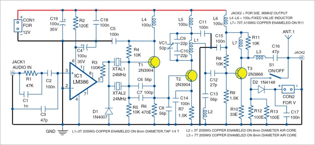
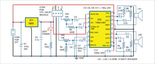
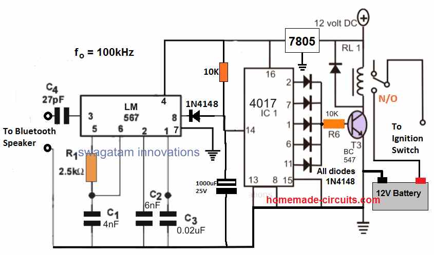
42 bluetooth transmitter and receiver circuit diagram
How to make a bluetooth audio receiver circuit, simple ... How to make a simple remote control amplifier using transistor 13003 and D882. Connect your phone to a mini homemade circuit. Make a bluetooth device at home... AT-LP60XBT User Manual - Audio-Technica as Bluetooth receiver devices). About pairing When connecting a new Bluetooth receiver device, you need to pair it with the product. Once the Bluetooth receiver device and the product are paired, you do not need to pair them again. However, in the following cases you will need to pair again even if the Bluetooth receiver device was paired once:
IR based Wireless Audio Transmitter and Receiver Circuit Diagram Circuit Operation. Only a few IR LEDs and resistors are directly attached to the audio source and battery in the transmission circuit. The connection of the audio jack to the circuit is one challenging work to encounter. A standard audio jack has three left and right earphone output pins, and the other is a grounded screen.

Bluetooth transmitter and receiver circuit diagram
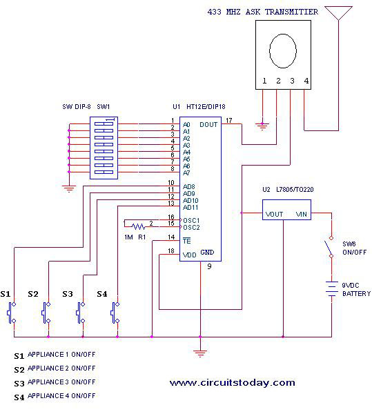
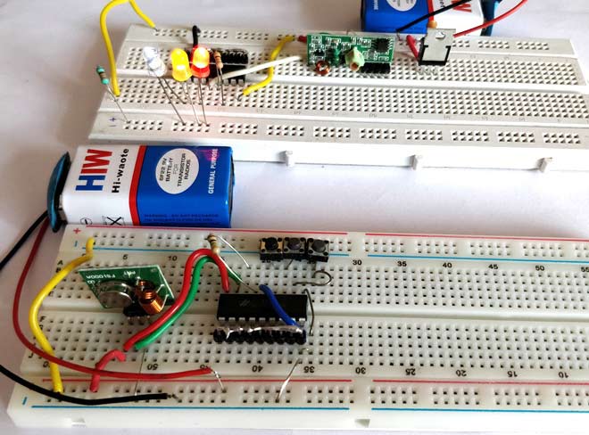
Top 30 DIY IoT Projects - From Basics to Advanced ... Complete project details with code and circuit diagram can be found in the given link: IoT Controlled LED using Google Firebase 2. NodeMCU Webserver to Control an LED. Now to take you one step ahead towards IoT development, this project includes building a web server to host a webpage, and control any appliance remotely from anywhere in the world. Bluetooth Function Generator Circuit - Homemade Circuit ... The Bluetooth Function Generator Circuit: The amplifier circuit consists of a popular op-amp IC 741 and two resistors which determines gain. The resistors R1 and R2 are well selected for best performance of the function generator, altering the values may lead to inconsistent wave generation at the output. RF Transmitter and Receiver Circuit | Circuit Digest 25.8.2017 · As you can see the RF Transmitter Circuit consists of the Encoder IC and RF Receiver circuit consists of the Decoder IC.Since the transmitter does not need a regulated 5V we have directly powered it with a 9V battery. Whereas in the receiver side we have used a 7805 +5V voltage regulator to regulate 5V from the 9V battery.
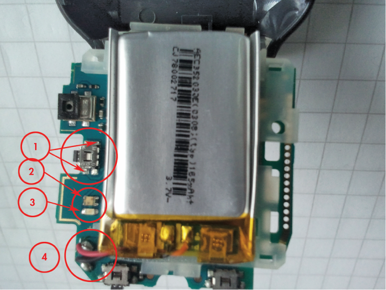
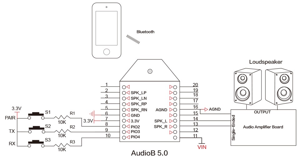
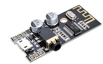
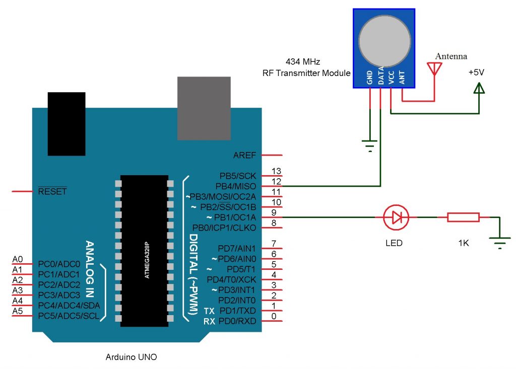
Bluetooth transmitter and receiver circuit diagram. 5 Bluetooth Circuit Basics Every Beginner Needs to Know ... Bluetooth transmitter circuit board. To be able to share files wirelessly, whether they are JMPEG or MP3, you must have a Bluetooth transmitter circuit board. Its basic function is to transfer certain files from one device to another. This board consists of wireless transmission, a regulated voltage and a sensor. Bluetooth Transmitter And Receiver Circuit Diagram Pdf ... bluetooth transmitter and receiver circuit diagram Making our projects Wireless always makes it to look cool and also extends the range in which it can be controlled. In this project we will learn how we can build wireless projects using a MHz RF module. These modules are cheap for its functions and are easily available. Build Your Own Bluetooth Audio Receiver : 6 Steps ... You need to disarm your bluetooth speaker to analice the circuit and to notice if it's hackable, as you can see in the picture, the blue board, is the bluetooth module, so begin seeking by there, search for the datasheet of the main IC of the bluetooth module so you can know the pinout and find out from where the audio come out. Ask Question Audio Transmitter And Receiver Circuit Diagram | Audio ... one is the transmitter circuit and the other is the receiver circuit, the transmitter circuit will be connected to the 3.5mm audio jack for audio input and the receiver circuit will be connect to a the complete circuit diagram for this wireless music transfer using ir leds project is given below it uses an antenna to capture radio waves, …
Bluetooth Technology - Electronic Circuits and Diagrams ... Piconets actually refer to the process called Personal Area Network (PAN), in which a network is created between all the devices which have Bluetooth facility with the range of transmission and reception. This method is started automatically by the devices and does not need a command from the user. Wireless Alarm Transmitter and Receiver Schematic Circuit ... The heart of the circuit (IC1) is a digital data coder. It outputs from its DOUT pin a binary sequence containing an address, coming from inputs A1-A5, and data reflecting the state of inputs D6-D9. The addresses are used here for the 'house' code, while data lines D7,D8,D9 code the transmitter number from 0-7. Bluetooth Receiver Circuit Diagram - U Wiring 28 Bluetooth Transmitter And Receiver Circuit Diagram. Bluetooth Audio Transmitter And Receiver Circuit Diagram. The NRF24L01 connection with the Arduino remains exactly the same. D1 signals that the transmitter is on and is a voltage stabilizer for the oscillator. As you can see the RF Transmitter Circuit consists of the Encoder IC and RF. Amazon.com: Bluetooth receiver and transmitter Bluetooth Transmitter Receiver, Aisidra V5.0 Bluetooth Adapter for Audio, 2-in-1 Bluetooth AUX Adapter for TV/Car/PC/MP3 Player/Home Theater/Switch, Low Latency, Pairs 2 Devices Simultaneously. 4.3 out of 5 stars. 1,171.
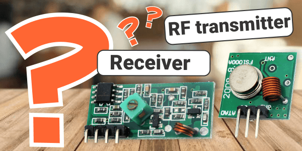
RF Transmitter and Receiver : 8 Steps (with Pictures ... RF Transmitter and Receiver: In this project, I will use RF modules with Pic 16f628a. It will be a short tutorial about rf. After you learn ho rf modules communicate with each other you can use these modules with pic microcontroller, ardunio or any microcontroller. I controlled… Wireless RF Module | RF Transmitter and Receiver | Latest ... Transmitter and the receiver are duly interfaced to two microcontrollers for data transfer. Features of RF Module: Receiver frequency 433MHz Receiver typical frequency 105Dbm Receiver supply current 3.5mA Low power consumption Receiver operating voltage 5v Transmitter frequency range 433.92MHz Transmitter supply voltage 3v~6v PDF Bluetooth transmitter and receiver circuit diagram pdf Bluetooth audio transmitter and receiver circuit diagram. Making our projects wirelessly makes it always seem fresh and also extends the range where it can be checked. Starting with the use of a normal IR LED for wireless control within a short distance up to an ESP8266 for the world HTTP control there are many ways to control something in ... Bluetooth Speaker Circuit Diagram - U Wiring The last major section of this circuit board is the Bluetooth section. Bluetooth Audio Transmitter And Receiver Circuit Diagram. An international agreement has been made for the use of industrial scientific and medical devices ISM to set aside a frequency band between 2402 GHz and 2480 GHz for Bluetooth.
How to build a Simple IR Transmitter and Receiver Circuit ... IR Receiver Circuit Diagram IR Receiver circuit is very simple we just need to connect a LED to the output of the TSOP1738, to test the receiver. We have use BC557 PNP transistor here, to reverse the effect of TSOP, means whenever the output is HIGH LED will be OFF and whenever it detects IR and output is low, LED will be ON.
Bluetooth Audio Transmitter And Receiver Circuit Diagram ... ir transmitter and receiver circuit diagram bluetooth audio simple fm audiob plus dc 5v module wireless headphones rf usb of the tv using only 2 make this speaker micro listening device 10 circuits long range to 5 quality stereo microphone or home theater serial hc 06 led li fi board how count as 4 0 template teardown dongle keeps au05 btm 80 …
PDF Bluetooth Audio Transmitter Receiver Circuit Diagram receiver circuit diagram, how to make an fm transmitter buildcircuit electronics, ir based wireless audio transmitter and receiver circuit, bluetooth transmitter schematic best place to find, top 10 bluetooth transmitters of 2019 video review, infrared transmitter receiver circuit pdf wordpress com, bluetooth wireless transmitter, amazon com fm
PDF Bluetooth Transmitter Receiver Circuit Diagram Bluetooth Transmitter Receiver Circuit Diagram DIY Wireless RC Remote Controller for Robots Quadcopter. Long Range IR Transmitter Circuit Diagram. Bluetooth® low energy and the automotive transformation. Lexikon der Mechatronik englisch deutsch fachlexika de. VE2ZAZ Bluetooth Headset with PTT for Amateur Radio. Wireless RF Remote Control ...
RF Transmitter and Receiver Circuit using RF Module ... 433MHz RF Receiver Circuit Diagram Circuit Description Transmitter Circuit The HT12E encoder IC VSS pin is connected to the power supply Ground (-) and the VDD is connected to the power supply VCC (+). IC A0 - A7 pins (pin 1 - 8) are connected to the Ground (-) to set the address at 0b00000000.
Build A Simple Wireless Bluetooth ... - Electronic Design Two wires for the Bluetooth headset's On/Off switch Three wires for the green and red bicolor LEDs (i.e., the common anode, green cathode, and red cathode) Two wires for the blue LED (anode and...
Bluetooth Circuits - Circuit Board Fabrication and PCB ... The Bluetooth Circuits Process ① The Pre-production Step ② Inner Layer Imaging ③ Inner Layer Etching ④ Inner Layer AOI We use the data (Gerber file) that you send us to create the production information for your customized boards. Our experts match your specifications with the capacities for compliance purposes. ⑤ Lamination ⑥ PCB Drilling
Bluetooth Circuit Board-How To Count As a High ... - OURPCB The Bluetooth transmitter circuit board contains options for battery charging, voltage regulation, audio amplification, and Bluetooth. The other functions of the speaker are carried out by the different parts of the main circuit board. The Bluetooth transmitter also comes with play and volume control buttons to give you control over your music.
Wireless Audio Transmitter And Receiver Circuit Diagram ... One is the transmitter circuit and the other is the receiver circuit, the transmitter circuit will be connected to the 3.5mm audio jack for audio input and the receiver circuit will be connect to a the complete circuit diagram for this wireless music transfer using ir leds project is given below It uses an antenna to capture radio waves ...
Bluetooth Transmitter And Receiver Circuit Diagram Pdf ... bluetooth transmitter and receiver circuit diagram Making our projects Wireless always makes it to look cool and also extends the range in which it can be controlled. In this project we will learn how we can build wireless projects using a MHz RF module. These modules are cheap for its functions and are easily available.
Bluetooth Audio Transmitter Circuit Diagram | Audio ... A block diagram of the system is described in Figure 1. Figure 1. Block diagram of wireless Bluetooth stereo audio system. This system is based on a stereo Class D audio amplifier which is driving a pair of 4Ω speakers. Determining the Output Power The output power requirement is 20WRMS (10WRMS per channel). One should note that measuring RMS …
Radio Transmitter and Receiver | Working | Block Diagram ... A power supply is provided for the oscillator and the final power amplifier. Figure 6. A block diagram representing various stages of a basic continuous wave radio transmitter. Following the action in Figure 6, the oscillator creates an ac sine wave at the desired frequency. This signal is called the carrier wave.
RF Transmitter and Receiver Circuit | Circuit Digest 25.8.2017 · As you can see the RF Transmitter Circuit consists of the Encoder IC and RF Receiver circuit consists of the Decoder IC.Since the transmitter does not need a regulated 5V we have directly powered it with a 9V battery. Whereas in the receiver side we have used a 7805 +5V voltage regulator to regulate 5V from the 9V battery.
Bluetooth Function Generator Circuit - Homemade Circuit ... The Bluetooth Function Generator Circuit: The amplifier circuit consists of a popular op-amp IC 741 and two resistors which determines gain. The resistors R1 and R2 are well selected for best performance of the function generator, altering the values may lead to inconsistent wave generation at the output.
Top 30 DIY IoT Projects - From Basics to Advanced ... Complete project details with code and circuit diagram can be found in the given link: IoT Controlled LED using Google Firebase 2. NodeMCU Webserver to Control an LED. Now to take you one step ahead towards IoT development, this project includes building a web server to host a webpage, and control any appliance remotely from anywhere in the world.














Comments
Post a Comment