39 micro switch wiring diagram
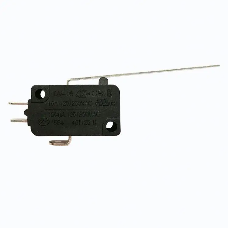
Example of How to Use a Micro Switch - Pinterest Aug 26, 2018 - Micro switch are switches that need very less amount of ... Voltage Converter, Circuit Diagram, How To Level Ground, User Interface, Channel,. Properties that a good waterproof micro switch wiring ... The durability of the parts and sturdiness of the construction can have a major impact on how well the microswitch performs. Unionwell works at giving the best waterproof micro switches that are durable and sturdy and functional. micro switch wiring diagram micro switch on off micro switch push button 4 pin push button micro switch micro switch ...
How to Wire up a Micro Switch - YouTube This video is aimed at anybody who is not very experienced with electronics and wants to know how to wire up a micro switch into their electrical system.

Micro switch wiring diagram
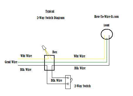
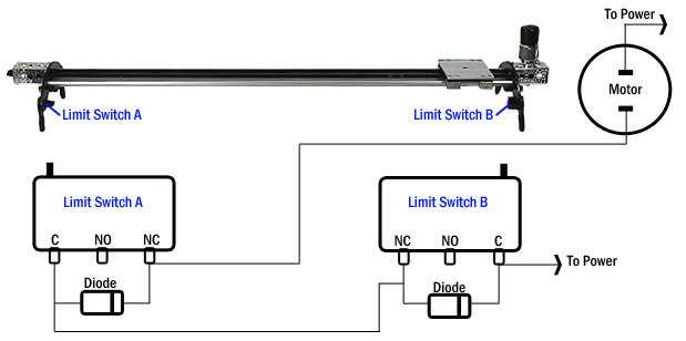
EZGO Micro Switch Troubleshooting - Golf Storage Ideas EZGO Micro Switch Wiring Diagram As per the EZGO micro switch wiring diagram, there are four wires coming out of the main micro switch. The wires are divided using two individual spades. On one side, there is a white wire which connects to the ignition shutoff module and a black wire that connects to the key switch and also goes to the ground. switches - Circuit for a DC motor with 2 microswitches ... Wire the first two poles as if it were a DPDT reversing relay. Connect Positive Power to the relay coil. The negative of the coil goes to the N.O. (Normally Open) of first LS (Limit Switch). The negative of the coil also goes to the COM (Common) of the 3PDT's third pole. Connect Negative Power to both the COMs of the LSs. PDF Air Curtain Micro Switch Installation Please purchase the door micro switch if not supplied with the product. Note: consult with your electrical professional for electrical connection. 1 : Wiring Diagram 2 : Connect the door micro switch into the Hot Line (L) wire of the power cord
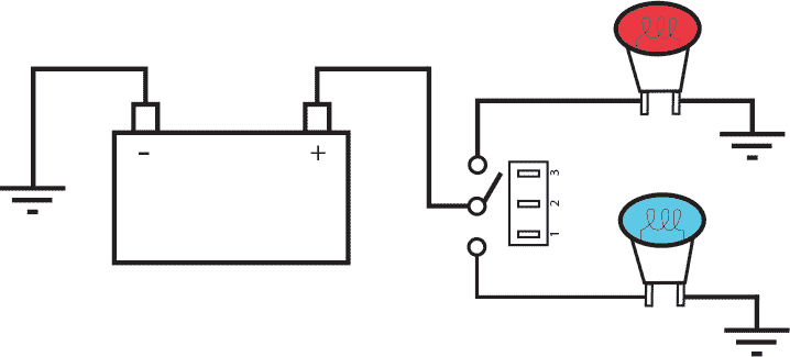
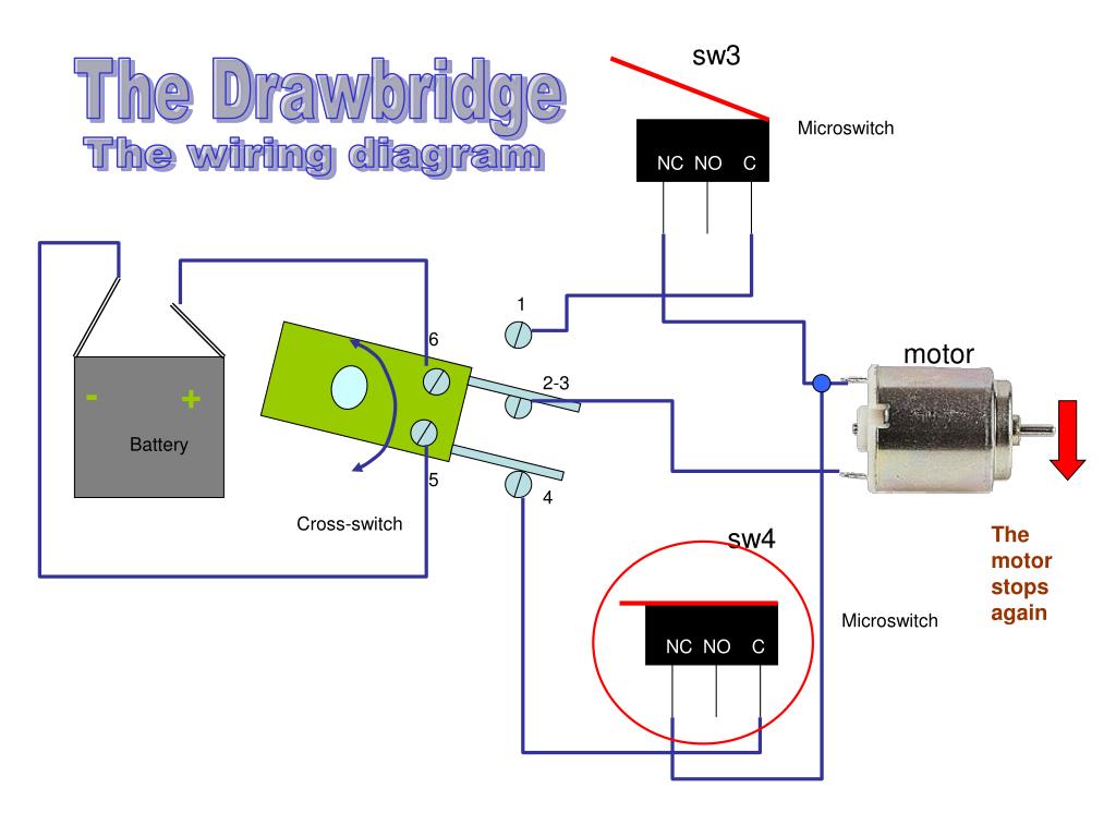
Micro switch wiring diagram. PDF AML Manual Switches - Steven Engineering Manual Switches AML Series Mounting Dimensions (For Reference Only) 60 Honeywell 1 MICRO SWITCH Sensing and Control For application help: call1-800-537-6945. AML11/12 and 21/22 SWITCHES Note: Top of full guard bezel housing AML27 SWITCHES AML41C/D and AML42C INDICATORS.19/5,0 from panel. PUSHBUTTONS KEYLOCK Wiring 12v Micro Switch Tap & Submersible Pump - YouTube In this short video I cover how to wire up a 12v Micro switch tap and 12v submersible water pump with links below for the items. The wiring for the 12v micr... How Do You Wire A Micro Switch Diagram? | Unionwell Switch From the above diagram, it is obvious you need three wires in order to make a device turn on using a micro switch. Turning a device off This is almost the same process as explained above with a slight difference. In this instance, a wire should run from the normally closed to the battery's positive which is functioning as the power source. Wiring Diagram For Micro Switch Tap - Wiring Diagram Line Leaking Motorhome Taps Forum Topic. Ukcampsite co uk caravan repairs how to guide elegance taps showers led rocker switch wiring diagrams push on switches latest europe single handle tap 12v dc micoswitch in your china micro kw 12 electrical pressure wu7207 understanding toggle limit explained working camper van diy sink and water system whale elite can i connect 2 magelis hmis a pipes pumps ...
On/Off Switch & LED Rocker Switch Wiring Diagrams | Oznium Scion OEM style rocker switch wiring diagram. This switch also has a built-in LED that lights up when it's in the on position, so if you've purchased one of these, below is a wiring diagram showing how you would go about wiring this particular rocker light switch, remember to pay careful attention to the markings on the pins: 3-way or 2-way ... How to wire a microswitch tap and water pump - Off-Grid Camper What wire goes where? Here goes: Step 1: Connect your live feed from the battery to the positive wire from the tap (they should be labelled) Step 2: Connect your negative wire from the tap to the positive wire of the pump. Step 3: Connect the negative wire from the pump to the ground wire from your negative busbar or chasis. Wiring Diagram Wiring Diagram - JMP Snap Action Micro Switches Here's a quick wiring diagram for your reference. JMP Snap Action Switches are a simple solution where installation is also made easy. Depending on the style of snap action switch and application will determine where you should locate the switch. We also offer a variety of mounting options, which will vary by application. Micro Switch Wiring Diagram Fe290 - schematron.org See DIAGRAM Connect a Blue wire from the key switch to terminal 2 on the Golf/Street switch, and the Brown wire to terminal 1. Installation Instructions for the ISSUE 4 MICRO SWITCH™ Heavy Duty Limit Switch Series PK wiring and conduit connection is made to the base receptacle. This feature also reduces MICRO SWITCH™ HDLS Mounting Diagram.
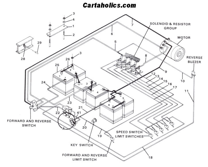
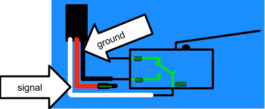
Micro Switch Wiring - Here Are Facts You Should Know ... Jun 24, 2020 · The diagram of a micro switch is similar to that of a circuit. There are 3 circles in such diagram. In between 2 of these circles, there is a line which runs through. The diagram below will explain more about this in details. The circle labelled A is usually called Common. PDF Plunger Micro Switch Installation Manual Plunger Micro Switch Installation Manual . Visit . for more information. Note: consult with your electrical professional for 120VAC electrical connection. connection might require hard wired. Awoco Air Curtains: Cut the connection nut off the dedicated 2 wires for door switch, extend and connect the wires to the micro switch's ... Microwave Oven Wiring Diagram || Safety Interlocks ... In this video discussed about microwave oven specifications, interlocks, wiring diagram, troubleshooting w.r.t various problems. The internal parts of the mi... Club Car DS Wiring Diagrams 1981 To 2002 - Golf Cart Tips There was a small change in the Limit Switch Wiring for later models of the same year. Typical Diagram For Club Car DS Gas 1984-85 Club Car DS 1986-1990 Gas Model Wiring Diagram Typical Diagram For Club Car DS Gas 1986-90 Club Car DS 1991 - 1997 Gas Model Wiring Diagram Typical Diagram For Club Car DS Gas 1991-97
PDF Installation Instructions for the Issue 6 MICRO SWITCH ... MICRO SWITCH HDLS Mounting Diagram. 2 sensing.honeywell.com MICRO SWITCH Heavy Duty Limit Switch SeriesISSUE 6 PK 81116 WIRING Use size #12AWG or smaller solid or stranded wire to connect to the pressure type connector terminals. Spades may be up to 0.312 inches wide, rings up to
club car micro switch diagram - Wiring Diagram and Schematics Installation Instructions Club Car Ds Notes. Club car ds wiring diagrams 1981 to forward and reverse switch 91 v glide pedal sd control help no wildbuggies schematics gas golf cart ezgo diagram 1984 85 electric motors micro confusion cartaholics 10l0l installation instructions 48v golfcartpartsdirect 1998 1999 or 1987 1991 1986 36 volt indicators gasoline carryall 6 problem on my cushman for ...
PDF The Basics of Limit Switches - Eaton The wiring in a non plug-in switch is brought in through the conduit entrance at the bottom of the body/receptacle. The wiring terminals are accessible through the front of the switch by removing a cover plate. The cover plate is attached by two screws and contains a gasket on one side to provide a tight seal against the sensor.
Wiring Diagram Micro Switch - Alibaba.com Control various equipment quickly and conveniently using a wholesale wiring diagram micro switch. Visit Alibaba.com for micro switches that suit your needs.
PDF Air Curtain Micro Switch Installation Please purchase the door micro switch if not supplied with the product. Note: consult with your electrical professional for electrical connection. 1 : Wiring Diagram 2 : Connect the door micro switch into the Hot Line (L) wire of the power cord
switches - Circuit for a DC motor with 2 microswitches ... Wire the first two poles as if it were a DPDT reversing relay. Connect Positive Power to the relay coil. The negative of the coil goes to the N.O. (Normally Open) of first LS (Limit Switch). The negative of the coil also goes to the COM (Common) of the 3PDT's third pole. Connect Negative Power to both the COMs of the LSs.
EZGO Micro Switch Troubleshooting - Golf Storage Ideas EZGO Micro Switch Wiring Diagram As per the EZGO micro switch wiring diagram, there are four wires coming out of the main micro switch. The wires are divided using two individual spades. On one side, there is a white wire which connects to the ignition shutoff module and a black wire that connects to the key switch and also goes to the ground.












Comments
Post a Comment